


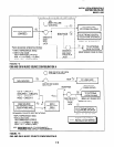
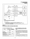
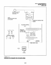

2. Installan HHEU PCBand HESC-65A cable
in the telephone per Section 100-816-206
before proceeding with Step 3.
3)
4
5)
6)
7)
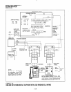
Connect Terminal 1 of the HESB TBl terminal
block to the red (+) wire of the HESC-65A
using a modular block.
Connect Terminal 2 of the HESBTBI terminal
block to the green (-) wire of the HESC-65A
using a modular block.
ConnectTerminal 8ofthe HESBTBI terminal
block to the yellow (L2) wire of the HESC65A
cable using a modular block.
Connect the HACU-120 power supply’s +12V
lead to Terminal 1 of the HESB TB2 terminal
block, and connect the power supply’s OV lead
to Terminal 2.
Plug the provided power cord into the power
supply and to a 117VAC, 60Hz power source.
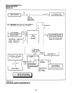
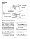
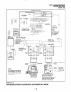
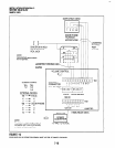
DK16 HESB Installation for Electronic Tele-
phone Loud Ring Bell (Figure 7-11):
1) On the HESB TBI terminal block: connect a
jumper between Terminals 6 and 7, and con-
nect anotherjumper between Terminals 5 and
8.
2) On the HESB TB2 terminal block, connect a
jumper between Terminals 4 and 5.
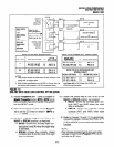
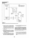
NOTES:
1. HESB connections made in steps 3-6
may be accomplished using the HESB
VOICE modular jack instead of the TBI
terminal block.
2. Install an HHEU PCB and HESC-65 (or
HESC-65A) cable in the telephone per
Section 100-816-206 before proceeding
with Step 3.
3) Connect Terminal 1 of the HESBTBI terminal
block to the red (+) wire of the HESC-65 cable
using a modular block.
4)
5)
6)
7)
8)
INSTALLATION-PERIPHERALS
SECTION 100-816-207
MARCH 1993
Connect Terminal 2 of the HESB TBI terminal
block to the green (-) wire of the HESC-65
cable using a modular block.
Connect Terminal 3 of the HESB TBl terminal
block to pin 3 of the electronic telephone’s
modular block (VOICE TIP).
Connect Terminal 4 of the HESB TBI terminal
block to Pin 4 of the electronic telephone’s
modular block (VOICE RING).
Connect the HACU-120 power supply’s +I 2V
lead to Terminal 1 of the HESB TB2 terminal
block, and connect the power supply’s OV lead
to Terminal 2.
Plug the provided power cord into the power
supply and to a 117VAC, 60Hz power source.
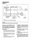
4.22 Loud Ringing Bell Test. Test the Loud Ring-
ing Bell installation in accordance with the following
steps:
1) Make a CO or station call to the station config-
ured for the loud ringing bell.
l
Ringing will be heard over the HESB.
2) Adjust the HESB volume control to the desired
level. (Screwdriver adjustment on back of
HESB and ring level control of associated
telephone.)
3) If ringing is heard at the station, but not over
the HESB, perform the following check while
the station is ringing:
a)
Using a suitable voltmeter, measure volt-
age across terminals 1 (+) and 2 (-) of the
HESB TBl terminal block.
l
Voltage indication should be 4.5 -
5.0 VDC.
NOTE:
Ringing stops once the call is manually an-
swered. There shouldbe NO voltage potential
across terminals I and 2.
b) If voltage is not as specified during ring-
ing, check that the telephone wiring con-
nections to the HESB have been made
properly (wires to terminals 1 and 2 of the
HESBTBl terminal blockmay have been
reversed).
7-13