


INSTALLATION-CONFIGURATION
SECTION 100-816-203
MARCH1993
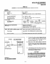
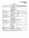
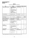
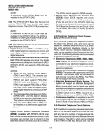
TABLE 3-C
DK8 KEY SERVICE UNIT COMPONENTS
item supports Connector Type
Standard Optional
Digital Telephone Circuits (4)
l
Digital Telephones (with 25pair Amphenol
J
or without PDIU-D12 or
ADM)
l
Stand-alone Data
Interface Units (PDIU-DS)
l
Door Phone Lock/Control
Unit (DDCB)
CO Line Circuits (2) 0 Loop Start CO Lines RJll Modular
J
Power Failure Transfer Interface
l
Standard Telephone RJll Modular
J
(one)*
Battery Backup Interface
l
Optional HPFB Battery Proprietary Interface HPFB
(one or two per system) Cable/Connector with cable
Music-On-Hold/BGM Interface
l
Music-on-hold/BGM RCA Jack
J
Source*
600 Ohm page Interface
l
Amplifier/Speaker RCA Jack
J
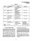
CO line CKT (l)/
l
Digital Telephones (with 25pair Amphenol
Digital Telephone CKT (2) (QCDU) or without PDIU-D12 or
(max. 2 QCDU per system) ADM)
J
l
Stand-alone Data
Interface Units (PDIU-DS)
l
Loop Start CO Line RJll Modular
Standard Telephone
l
Standard Telephones*
Interface Unit (QSTU)
l
Other Single-line Devices* 25pair Amphenol
) 2 standard telephone circuits
l
Fax Machine*
J
(1 max.) QSTU per system
l
Voice Mail Devices
l
Alternate BGM source*
DTMF/ABR Tone Receiver
l
Automatic Busy Redial
Internal
(3-Receiver CKT per QRCU )
l
Standard telephone ports
. DISA
Control Relay
One of the following:
25-pair Amphenol
l
Night Relay
l
External Page Mute
J
l
MOH Control Relay
Conference Circuit Interface Unit
l
2 Simultaneous
Internal
(QCNU)
Conferences
J
SMDRKTY interface Unit (QSMU)
l
SMDR Printer*, or 6-pin Modular
(Requires PPTC)
l
Maintenance Terminal* or (PPTC adaptor)
l
Modem*
*Customer supplied equipment not offered by Toshiba Telecommunication Systems Division.
J
J
3-3