


INSTALLATION-STATION APPARATUS
SECTION 100-816-206
MARCH 1993
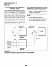
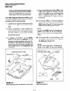
4) Connect the telephone to the wall modular
connector with a cord approximately four
inches long (available at most telephone sup-
ply companies). Route the cord into the hol-
low portion of the base.
5) Mount the telephone on the wall mounting
modular connector plate.
3 DIGITAL TELEPHONE UPGRADES
3.00 This section describes how to upgrade and
configure 2000- and lOOO-series Digital Tele-
phones for features and options.
3.10 Simultaneous Voice and Data Upgrade
(PDIU-D12 and PDIU-DI)
3.11
Both the 2000- and 1 OOO-series Digital Tele-
phones can be upgraded with an integrated data
interface unit to transmit and receive simultaneous
voice and data calls. There are two versions of the
integrated unit: the PDIU-DI and the PDIU-D12.
The 2000-series telephones can only be equipped
with a PDIU-D12, and the 1 OOO-series telephones
can only be equipped with a PDIU-DI. Asynchro-
nous devices, such as personal computers (PC)
and terminals, can be connected to the standard
RS-232 connector of the PDIUDl(2). Station us-
ers are able to transmit and receive W-232 data
over the single wire pair of the PDIUDI(2)-equipped
telephone.
3.12 Data calls can be manually dialed with a
Data Call button and disconnected with a Data
Release button on the telephone; or, data and
voice calls can be dialed from the keyboard of the
terminal or PC using standard “AT” commands.
Digital telephones may also be assigned a Modem
button to reserve a modem or monitor modem
availability and status. Assign feature buttons to
telephones with
Program 39.
NOTES:
1. 1 OOO- and2000series Digital Telephones
equipped with a PDIUDl(2) cannot be
wall-mounted or equipped with an Add-
On-Module (ADM), or DVSU for OCA. A
2000series digital telephone equipped
with a PDIU-Dl2 can support an HHEU at
the same time, but cannot support a
DVSU. A 1000~series Digital Telephone
equipped with a PDIU-DI cannot support
an HHEU, ADM, or a DVSU for OCA.
2. PDKUl circuits 1 - 7 only can support
PDIU-Dl(2)s, but all PDKU2and base unit
digital circuits, can support PDIU-Dl(2)s.
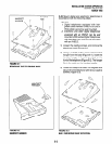
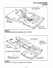
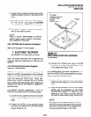
3.13 PDIU-Dl(2) Installation.
Install the inte-
grated data interface unit (PDIU-DI for 1 OOO-series
and PDIU-D12 for 2000series) in accordance with
the following steps:
1)
2)
3)
4)
5)
Loosen the four captive screws securing the
digital telephone base and remove it (Figure
6-l).
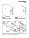
Refer to Figure 6-4for 2000series telephones
or Figure 6-5 for 1 OOO-series telephones, and
insert the two integrated unit wire plugs into
the connectors on the printed circuit board
(PCB) in the telephone (observing the red
wire for correct positioning).
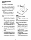
Attach the integrated unit to the bottom of the
telephone and secure with the four captive
screws.
Remove the telephone number directory tray
from the original telephone base and install it
on the integrated unit telephone base. Bend
the tray by squeezing its sides so it bows
slightly to remove and re-install (Figure 6-4 or
6-5).
Check Table 8-D in Section
100-816-208;
install 2-pair house cable (or external power)
and 2-pair modular cord (supplied with PDIU-
DI) if required to achieve maximum distance.
3.14 Integrated Data Interface Unit Program-
ming Overview
Program 39
l
Assigns the Data Call, Data Release, and Mo-
dem buttons.
Programs 20 and 22
l
Used for data interface unit assignments.
6-4