


10.13 Installation instructions for these devices are
provided in Paragraphs 10.40 thru 10.70. Call paths
and scenarios for five types of data test calls are
provided in Paragraphs 10.82 - 10.86. Step-by-step
data calling procedures are provided in the Data
Interface User Guide in the Installation & Mainte-
nance Manual, Operating Procedures.
10.20 EIA Interface Leads (Signals)
10.21
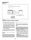
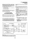
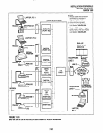
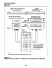
Both DlUs operate with nine standard EIA
RS-232 interface leads (signals) on which signal-
ing data is transmitted and received. DlUs connect
to serial data devices with standard RS-232 cables,
available from telephone supply stores (see Fig-
ures 7-25 - 7-30). The PDIU-DVPDIU-DS requires
nine signals for some applications, but can function
with eight using modular cords and connectors with
RJ45/DB25 adapters for other applications. If un-
certain which signals are necessary for an applica-
tion, all nine should be connected.
IMPORTANT NOTES!
1. The PDIU-DI is always a DCE device;
the PDIU-DS may be a DTE or DCE,
depending on how its internal jumpers
(1 - 9) are configured.
2. In the descriptions below, when a sig-
nal is ON, its potential is about seven
volts positive relative to signal ground
(pin 7); when a signal is OFF, it is about
7 volts negative relative to the signal
ground (pin 7).
Frame Ground (FG, Pin 1):
The FG signal (EIA
circuit AA) is a protective or safety ground which is
bonded to the PDIU-DVPDIU-DS PCB. If required
by local codes, the FG should be connected to
external ground.
Signal Ground (SG, Pin
7): The SG signal (EIA
circuit AB) establishes the common ground refer-
ence for all other PDIU and data device signals
and must be wired for all applications.
Transmit Data (TD, Pin
2): DTE devices transmit
and DCE devices receive data on the TD lead (EIA
circuit BA). Before the DTE device can transmit
the TD signal, the RTS, CTS, DSR, and DTR
signals (all discussed below) must be ON. The TD
signal is OFF in the idle state.
INSTALLATION-PERIPHERALS
SECTION 100-816-207
MARCH 1993
Receive Data (RD, Pin 3):
The DCE device
transmits data to the DTE device on the RD lead
(EIA circuit BB); the DTE receives data on the RD.
Request to Send (RTS, Pin
4): Some DTE de-
vices send an RTS signal (EIA circuit CA) to the
DCE device when they are ready to transmit data
on the TD lead. If the DTE device does not
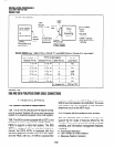
generate the RTS signal, the DIU DIP switch
SWI-4
should be set ON to inform the DIU.
Sometimes, the DTE/DCE device may use RTS/
CTS for Ready/Busy type flow control, in these
cases DIP switch
SWl-4
should be OFF (see
Figure 7-32 for DIP switch information).
Clear to Send (CTS, Pin 5):
The DCE device sends
the CTS signal (EIA circuit CB) which indicates
that it is prepared to transmit data to the line side.
The DCE device sends this signal only when it
receives the RTS signal from the DTE device.
Sometimes, the DTUDCE device may use RTS/
CTS for Ready/Busy type flow control; in these
cases, dip switch
SWl-4
should be OFF (see Fig-
ure 7-32 for DIP switch information).
Data Set Ready (DSR, Pin
6): When connected
to the communication channel and prepared to
exchange control characters to initiate data trans-
mission, the DCE device sends the DSR signal
(EIAcircuit CC) to the DTE device. If the PDIU DIP
switch
SW1
-2 is set ON, DSR will be ON continu-
ously; if the switch is set OFF, DSR follows DTR
(if DSR is ON, DTR is ON, etc.)
SWl-2
should be
OFF in most cases (see Figure 7-32for DIP switch
information).
Data Carrier Detect (DCD, Pin 8):
The DCE de-
vice sends the DCD signal (DCD, Pin 8) when
receiving the carrier signal on the line side. Before
transmitting or receiving data, most DTE devices
require that the DCD be ON. If the carrier signal is
removed by the remote end or lost due to a fault
condition on the line, the DCE notifies the DTE
device by an OFF condition with the DCD signal;
PDIU DIP switch
SWI-2
is set ON to set the DCD
ON continuously; if set OFF, the DCD signal will
only be ON when connection between two DlUs is
established and OFF when a connection is not
established.
SWl-2
is set OFF when the DTE/
DCE uses the DTWDSR signals for Ready/Busy
flow control (see Figure 7-32 for DIP switch in-
formation).
7-35