


INSTALLATION-DK 16 KSU & PCB
SECTION 100-816-205
MARCH 1993
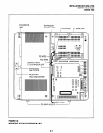
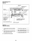
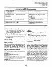
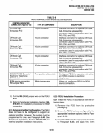
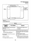
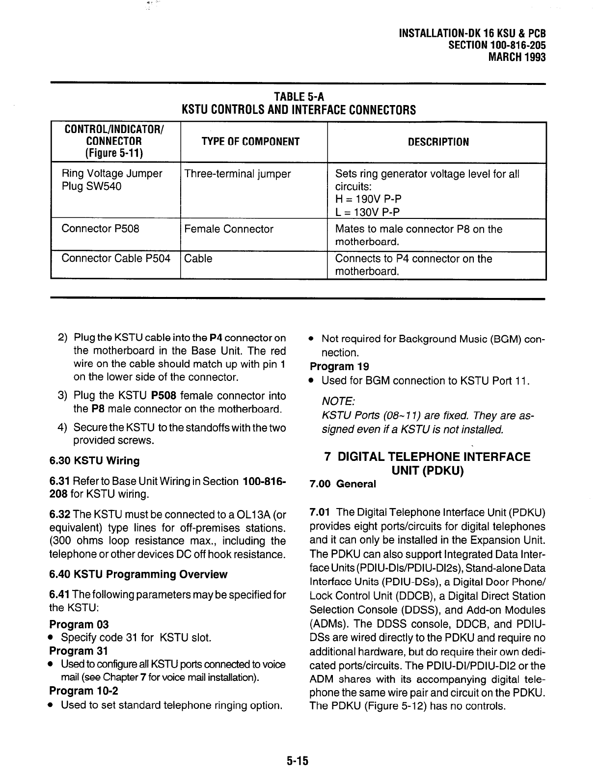
TABLE5-A
KSTU CONTROLSANOINTERFACECONNECTORS
CONTROL/INDICATOR/
CONNECTOR
(Figure 5-11)
TYPE OF COMPONENT
DESCRIPTION
Ring Voltage Jumper
Plug SW540
Connector P508
Three-terminal jumper
Female Connector
Sets ring generator voltage level for all
circuits:
H=190VP-P
L = 13ov P-P
Mates to male connector P8 on the
motherboard.
Connector Cable P504 Cable
Connects to P4 connector on the
motherboard.
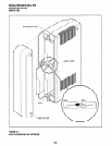
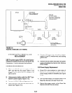
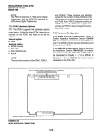
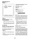
2) Plug the KSTU cable into the P4 connector on
the motherboard in the Base Unit. The red
wire on the cable should match up with pin 1
on the lower side of the connector.
3) Plug the KSTU P508 female connector into
the P8 male connector on the motherboard.
4) Secure the KSTU to the standoffs with the two
provided screws.
6.30 KSTU Wiring
6.31
Refer to Base Unit Wiring in Section 100-816-
208 for KSTU wiring.
6.32 The KSTU must be connected to a OL13A (or
equivalent) type lines for off-premises stations.
(300 ohms loop resistance max., including the
telephone or other devices DC off hook resistance.
6.40 KSTU Programming Overview
6.41 The following parameters may be specified for
the KSTU:
Program 03
l
Specify code 31 for KSTU slot.
Program 31
l
Used to configure all KSTU ports connected to voice
mail (see Chapter 7 for voice mail installation).
Program 1 O-2
l
Used to set standard telephone ringing option.
0 Not required for Background Music (BGM) con-
nection.
Program 19
l
Used for BGM connection to KSTU Port 11.
/VOTE:
KSTU Ports (OB- 1 I) are fixed. They are as-
signed even if a KSTU is not installed.
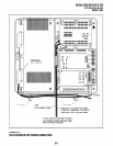
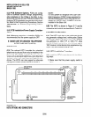
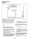
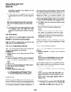
7 DIGITAL TELEPHONE liTERFACE
UNIT (PDKU)
7.00 General
7.01
The Digital Telephone Interface Unit (PDKU)
provides eight ports/circuits for digital telephones
and it can only be installed in the Expansion Unit.
The PDKU can also support Integrated Data Inter-
face Units (PDIU-Dls/PDIU-Dl2s), Stand-alone Data
Interface Units (PDIU-DSs), a Digital Door Phone/
Lock Control Unit (DDCB), a Digital Direct Station
Selection Console (DDSS), and Add-on Modules
(ADMs). The DDSS console, DDCB, and PDIU-
DSs are wired directly to the PDKU and require no
additional hardware, but do require their own dedi-
cated ports/circuits. The PDIU-DI/PDIU-D12 or the
ADM shares with its accompanying digital tele-
phone the same wire pair and circuit on the PDKU.
The PDKU (Figure 5-12) has no controls.
5-15