


table does not need to be defined in addition to
the area codes in Program 51, but it may. In the
second case, the plan may only pertain to
exception office codes for certain area codes.
Example I-In the first example, office code ex-
ception tables will be defined to the area code
table. Use the continuation sheet to define the
exception office codes. As many as eight of the
office code exception tables may be linked to a
plan, but each exception table may only be
used once. When using the continuation sheet,
be sure that the same exception table is not
assigned to more than one plan.
l
Turn to the continuation sheet (that follows
plan 8 record sheet).
l
Determine the plan number where the ex-
ception office codes will be rooted.
l
Fill in the area code of the exception office
codes in the spaces provided by the correct
plan number. These office codes will be
routed differently than the overall area code.
l
Enter the specific office codes that are to be
routed differently.
Example 2-In the second example, the route
plan only applies to office code exceptions. The
first office code exception table may be docu-
mented on the LCR Plan record sheet:
0
Check the box on the record sheet next to
Office Code Exception Table number.
Enter the number of the exception table (1
- 8). Make sure this table number is not
entered on any other plan or on the continu-
ation sheet.
0
0
Enter the applicable area code.
Enter the specific office codes that are to be
routed differently than the area code.
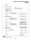
7.36
Program 53-LCR Schedule Assign-
ments. This program assigns up to three time
schedules to each plan. Each time schedule con-
sists of four different route definition choices (de-
fined in Program 54) available to the four station
groups (defined in Program 56). It may be helpful
to complete Program 54 portions of the plans and
Program 56 before proceeding.
Typical installation without time scheduling
feature-In most cases, an installation will not
require use of the time schedule feature. To
reflect this on the record sheets for plans 1 - 8:
SECTION 100-816-302
MARCH 1993
Enter the same Schedule Start Times for
Schedules 1 and 2. Use military time, in the
format HH:MM (Hours:Minutes). Fill in all
four digits. Initialized data assigns “0000” to
all times.
l
If LCR software sees schedules 1 and 2
have the same start times, then it only
looks at schedule 1 for route definitions.
Enter Route Definition Numbers for
Schedules 1 and 2. Four definitions may be
entered for each group.
LCR Station (Class) Groups 1 - 4 are
assigned in Program 56.
LCR Route Definition numbers 1 - 4 are
defined in Program 54.
The order in which the route definitions
are entered defines the order of LCR
line selection. The most desirable route
should be entered in the leftmost posi-
tion, and the least desirable route in the
rightmost position.
If “1” is assigned to Station Group 1 and
1 for route definition only, then those
assigned will only be able to use route
definition 1, thereby restricting them
during times that route definition 1 is not
allowed.
Keep in mind that the route definition
number is being entered, not the CO
line group number. The definitions are
assigned in Program 54.
Installation requiring timeschedulingfeature-
When an installation requires the time scheduling
feature to be programmed, three “shifts” of route
definitions can be assigned per station group. To
reflect this on the record sheet, substitute Step 1
of the procedure described for the typical cus-
tomer with the following:
1: Enter the Schedule Start Times for
Schedules 1, 2 and 3. Use military time, in
the format HH:MM (Hours:Minutes). Fill in all
four digits. Initialized data assigns “0000” to
all times.
l
Start time for schedule 2 is the stop time
for schedule 1.
l
Start time for schedule 3 is the stop time
for schedule 2.
l
Start time for schedule 1 is the stop time
for schedule 3.
2-33