


INSTALLATION-WIRING DIAGRAMS
SECTION lOO-816-208
MARCH1993
TOPDKUIKCDUIBASE UNIT
W/FEMALE CONNECTOR BR”
CIRCUIT 2 TO DKTZ
CIRCUIT 3 TO
DKT3
CIRCUIT 4 TO DKT4
B
L
Y
CIRCUIT 5 TO DKT5
TERMINAL, ETC.
CIRCUIT 6 TO DKT6
z /, BK-0 I 37
PR &DD. POWER1
- ---
TELEPHONE (DKT
1)
(WITH OR WITHOUT
PDIU-DIIPDIU-Dl2)
CIRCUIT 8 TO DKT8
. .IACKFTFll TWISTFD PAIRS
66M150 SPLIT BLOCK
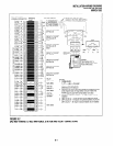
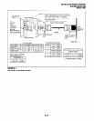
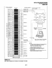
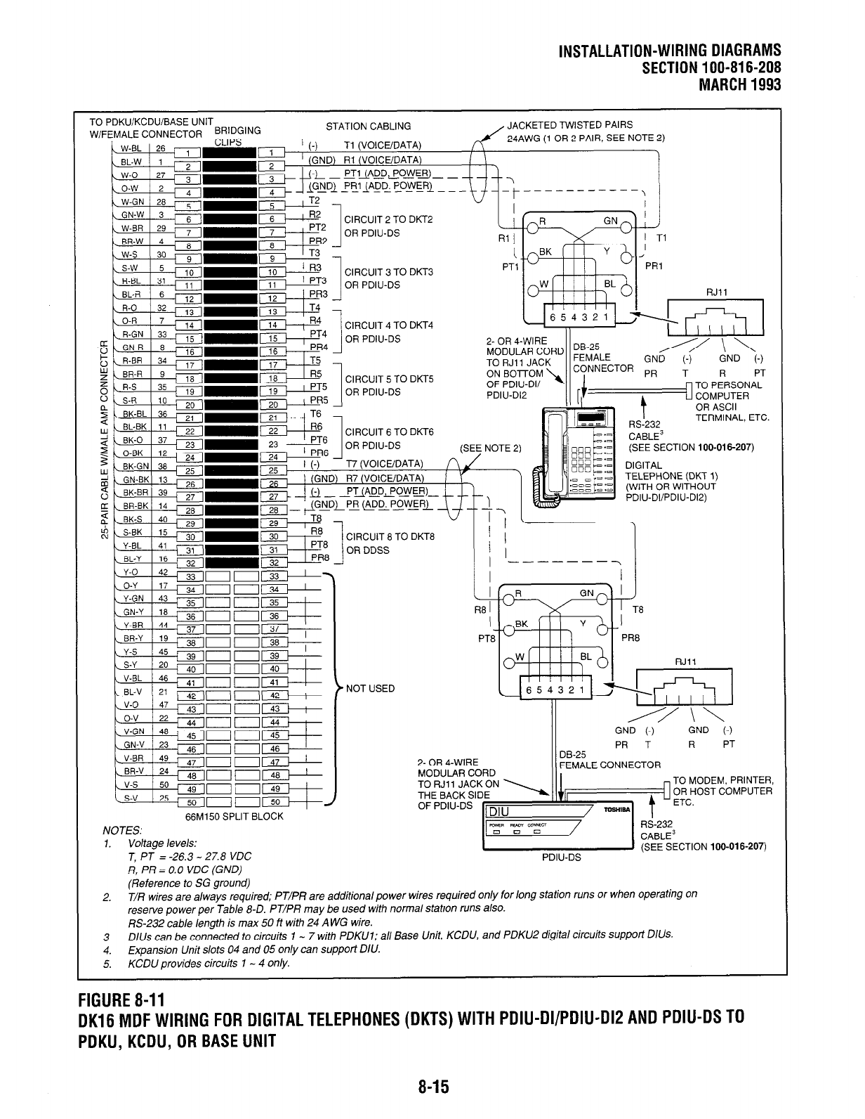
NOTES:
1. Voltage levels:
T PJ = -26.3 - 27.8 VDC
’ NOT USED
RJll
PR T R
PT
(/o-I-:- ~~~~EcTloN
,oo~o,6~207)
PDIU-DS
!=i, PR = 0.0 VDC (GND)
(Reference to SG ground)
2. T/R wires are always required; PJ/PR are additional power wires required only for long station runs or when operating on
reserve power per Jab/e 8-D. PT/PR may be used with normal station runs also.
RS-232 cable length is max 50 ft with 24 A WG wire.
3 D/Us can be connected to circuits 1 - 7 with PDKUl; a// Base Unit, KCDU, and PDKUZ digital circuits support D/Us.
4.
Expansion Unit slots 04 and 05 only can support D/U.
5. KCDU provides circuits 1 - 4 only.
FIGURE 8-11
OK16 MDF WIRING FOR DIGITAL TELEPHONES (DKTS) WITH PDIU-DI/PDIU-DIP AND PDIU-OS TO
PDKU, KCDU, OR BASE UNIT
8-15