


INSTALLATION-OK8 KSU & PCB
SECTION 100-816-204
MARCH 1993
11.40 QSMU Wiring
11.41
Refer to Peripheral Equipment Installation
(Section
100-816-207, SMDR)
and Remote Main-
tenance (Section
100-816-600, TTY)
for QSMU
wiring/interconnecting details.
11.50 QSMU Programming Overview
11.51
The following parameters may be specified,
through programming, for the QSMU:
Program 60
0 Assigns SMDR options.
Program 1 O-3
l
LED04-SMDR/TTY Select option.
11.60 Device Communication Parameters
11.61
Set the communication parameters for the
device connected tot he QSMU SMDR/TTY jack as
follows:
l
TTY: 7 Bits, I-Stop Bit, Even Parity
l
SMDR: 8 Bits, l-Stop Bit, Odd Parity
. TTYSMDR: 1200 bps
12 BUILT-IN CO LINE, DIGITAL TELE-
PHONE, AND OTHER CIRCUITS
12.00 General
12.01
As mentioned in Paragraph 6, the KSU comes
standard with two CO lines and four digital tele-
phone circuits already installed.
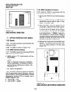
12.10 Built-in CO Line Circuits
12.11
The two standard loop start CO line circuits
are integrated into the KSU motherboard and are
identical to the QCDU CO line circuits. For wiring
and programming considerations, see the QCDU
instructions in Paragraph 7.
12.20 Built-in Digital Telephone Circuits
12.21
The four digital telephone circuits that come
standard with the system are integrated into the
motherboard in the KSU. These circuits are identi-
cal to the digital circuits found on the QCDU. The
motherboard does not have to be configured for the
digital circuits to operate. For wiring and program-
ming considerations, see the QCDU instructions in
Paragraph 7.
12.30 KSU Motherboard CO Line/Digital
Station Circuit Wiring
12.31
Refer to Section 100-816-208 for details.
l
Station circuits: DK8 MDF to KSU Amphenol
Wiring Diagram
l
CO lines: DK8 MDF TO CO Line (KSU and
QCDU) Wiring Diagram
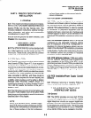
12.40 Power Failure Telephone Installation
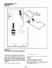
1) Remove the RJ11 cover (Figure 4-9) from the
PFT jack and store the jack cover.
2) Connect the power failure telephone (500/
2500-type standard telephone to the PFT jack.
(Refer to the DK8 MDF to CO Line Wiring
Diagram in Section
100-816-208.
12.50 Music-On-Hold (MOH)/Backgrounci
Music (BGM) Source Connection
12.51
Connect the MOH/BGM source to the MOH
RCA jack (Figure 4-7) in accordance with Music
Source Configuration A in Section
100-816-207.
12.60 External Page Output Connection
12.61
Connect the external page system to the
6OOQ PAGE RCA output jack (Figure 4-7) to an
external amplifier in accordance with the External
Page Installation guidelines in Section
100-816-207.
4-17