


INSTALLATION-DK 16 KSU & PCB
SECTION 100-816-205
MARCH 1993
16 KCOU REMOVAL AND
REPLACEMENT
16.00 General
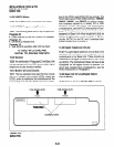
16.01
The KCOU comes factory-installed in the
Base Key Service Unit (Figure 5-3); if necessary,
it can be removed and replaced.
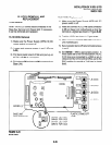
16.10 KCOU Removal
16.20 KCOU Replacement
1) Make sure the Power Supply (KPSU16) DC
power switch is off.
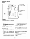
2) Mate and connect KCOU P6 cable connector
to P6 on Base Unit motherboard so that the
red wire is aligned as shown in Figure 5-23.
3) Position KCOU as shown in Figure 5-23.
1) Make sure the Power Supply (KPSUIG) DC
power switch is turned off.
2) Loosen and remove screws 1 and 2 (Figure
5-23).
3) Pull back plastic stand-off tab and pull up on
KCOU until P7 is unplugged.
4) Pull wires on
P6
and remove
P6
connector from
Base Unit.
4) Mate and connect KCOU
P7
to
P7
on the Base
Unit motherboard.
5) Secure plastic stand-off tab and install screws
1 and 2.
6) Set SW400 - 475 to appropriate position. In
most cases set to the normal position (NOR);
if CO lines are connected to a PBX or are in
close proximity to the Central Office, set to the
PAD position to provide a 3 db loss in signal
level.
1 - ‘---Ir--‘------
KCOU
w
Ii-
PLASTIC STAND-OFF
J4 (C04)
J3 (C04)
J2 (C04)
Jl (C04)
MOTHERBOARD
SW400 FOR CO1
(TAB)
SW425 FOR CO2
SW450 FOR CO3
SW475 FOR CO4
FIGURE 5-23
KCOU PCB
5-35