


INSTALLATION-PERIPHERALS
SECTION 100-816-207
MARCH 1993
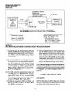
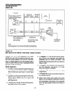
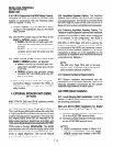
PIOU PCB
SELECT RELAY FUNCTION
WITH PROGRAM 77-l
DOOR
LOCK OR EXTERNAL
PAGE CONTROL
1 MAKE - 1
PIOU 25 PR.
MDF 66M
CONNECTIONS
BLOCK
PIN NO.
COLOR PIN N0.s
PAGE
AMPLIFIER
I I
tt
32 R-O
13
I I BGM MUTE
I I
DOOR
7 AD
a.4
LOCK
TAPE
PI AVER
I
II I
1 CONTROL
I L-IL,,
I I-t-t-m
NH.R 11 g
’ SELECT RELAY FUNCTION
WITH PROGRAM 77-l:
NIGHT RELAY OR
MOH CONTROL
CONNECTIONS
ALL WIRES SHOULD
BE JACKETED 24 AWG
TWISTED PAIRS
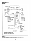
NOTE:
Dotted lines and solid lines differentiate optional connections
where applicable; do not connect both options simultaneously.
BELL
TO MUSIC-ON-
HOLD INPUT
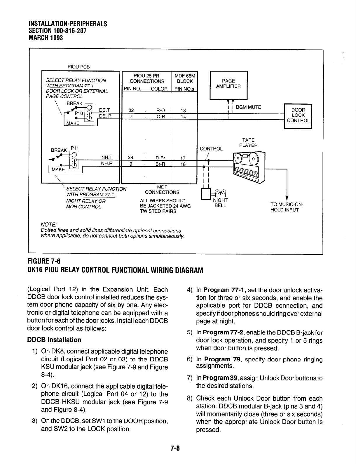
FIGURE 7-6
DK16 PIDU RELAY CONTROL FUNCTIONAL WIRING DIAGRAM
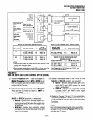
(Logical Port 12) in the Expansion Unit. Each
DDCB door lock control installed reduces the sys-
tem door phone capacity of six by one. Any elec-
tronic or digital telephone can be equipped with a
button for each of the door locks. Install each DDCB
door lock control as follows:
DDCB
Installation
1) On DK8, connect applicable digital telephone
circuit (Logical Port 02 or 03) to the DDCB
KSU modular jack (see Figure 7-9 and Figure
8-4).
2) On DK16, connect the applicable digital tele-
phone circuit (Logical Port 04 or 12) to the
DDCB HKSU modular jack (see Figure 7-9
and Figure 8-4).
3) On the DDCB, set SW1 to the DOOR position,
and SW2 to the LOCK position.
7-8
4) In Program 77-1, set the door unlock activa-
tion for three or six seconds, and enable the
applicable port for DDCB connection, and
specify if door phones should ring over external
page at night.
5) In Program 77-2, enable the DDCB B-jack for
door lock operation, and specify 1 or 5 rings
when door button is pressed.
6) In Program 79, specify door phone ringing
assignments.
7) In Program 39, assign Unlock Door buttons to
the desired stations.
8) Check each Unlock Door button from each
station: DDCB modular B-jack (pins 3 and 4)
will momentarily close (three or six seconds)
when the appropriate Unlock Door button is
pressed.