


INSTALLATION-PERIPHERALS
SECTION 100-816-207
MARCH 1993
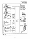
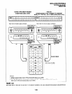
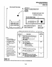
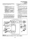
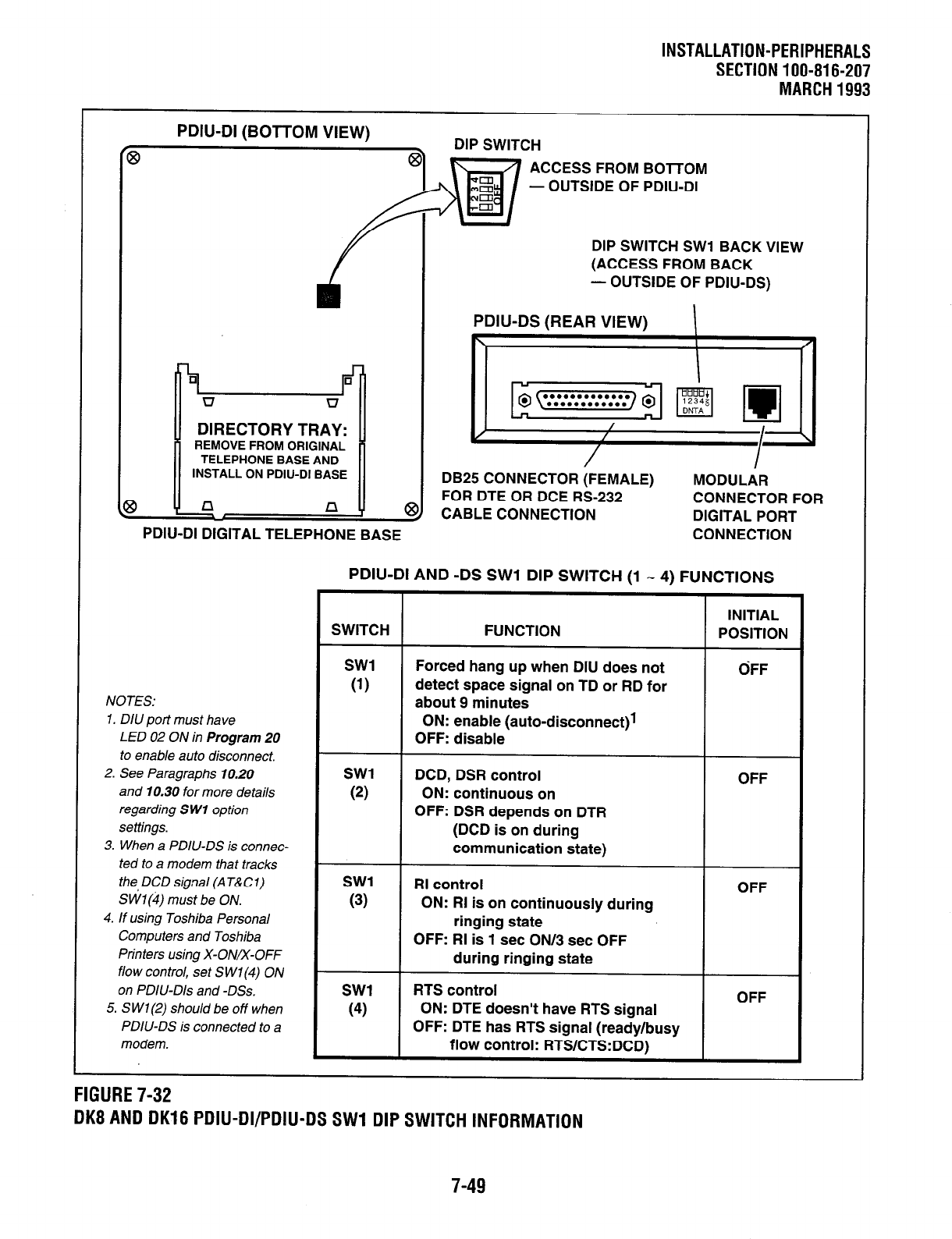
PDIU-DI
(BOTTOM VIEW)
DIP SWITCH
ACCESS FROM BOTTOM
- OUTSIDE OF PDIU-DI
DIP SWITCH SW1 BACK VIEW
(ACCESS FROM BACK
- OUTSIDE OF PDIU-DS)
I
n
DIRECTORY TRAY:
REMOVE FROM ORIGINAL
TELEPHONE BASE AND
INSTALL ON PDIU-DI BASE
n
PDIU-DI DIGITAL TELEPHONE BASE
PDIU-DS (REAR
VIEW
\
DB25 CONNECTOR (FEMALE) MODULAR
FOR DTE OR DCE RS-232
CONNECTOR FOR
CABLE CONNECTION
DIGITAL PORT
CONNECTION
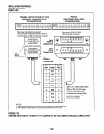
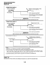
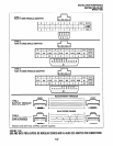
PDIU-DI AND -DS SW1 DIP SWITCH (1 w 4) FUNCTIONS
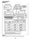
NOTES:
1. DIU port must have
LED 02 ON in Program 20
to enable auto disconnect.
2. See Paragraphs 10.20
and 10.30 for more details
regarding S WI option
settings.
3. When a PDIU-DS is connec-
ted to a modem that tracks
the, DCD signal (AT&Cl)
S Wl(4) must be ON.
4. If using Toshiba Personal
Computers and Toshiba
Printers using X-ON/x-OFF
flow control, set SWl(4) ON
on PDIU-Dls and -DSs.
5. S Wl(2) should be off when
PDIU-DS is connected to a
modem.
SWITCH FUNCTION
SW1
(1)
SW1
(2)
SW1
(3)
SW1
(4)
Forced hang up when DIU does not
detect space signal on TD or RD for
about 9 minutes
ON: enable (auto-disconnect)1
OFF: disable
DCD, DSR control
ON: continuous on
OFF: DSR depends on DTR
(DCD is on during
communication state)
RI control
ON: RI is on continuously during
ringing state
OFF: RI is 1 set ON/3 set OFF
during ringing state
RTS control
ON: DTE doesn’t have RTS signal
OFF: DTE has RTS signal (ready/busy
flow control: RTS/CTS:DCD)
INITIAL
POSITION
GFF
OFF
OFF
OFF
FIGURE 7-32
DK8 AND DK16 PDIU-DI/PDlU-DS SW1 DIP SWITCH INFORMATION
7-49