


INSTALLATION-DK8 KSU & PCB
SECTION 100-816-204
MARCH 1993
DK8RCUlAElV.1[70
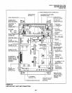
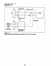
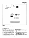
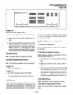
FlGURE4-11
QRCU INTERFACE CONNECTORS
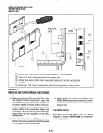
1) Remove the PCB from its protective packaging.
2) Make sure that the power supply switch is
OFF.
3) Align and insert QRCU connectors
Jl
and J2
into motherboard connectors
515
and J16
respectively (note the component side place-
ment in Figure 4-7), and apply firm, even
pressure to ensure proper mating of connec-
tors. Push down until connectors lock together.
9.30 QRCU Wiring
9.31
The QRCU does not require any wiring.
9.40 QRCU Programming Overview
9.41
The following parameters may be specified:
Program 12
l
Set QRCU release time.
Program 15
l
Sets QRCU operation after CO line flash.
10 CONFERENCE CIRCUITS (QCNU)
10.00 General
10.01
The QCNU provides two conference circuits
which allow two simultaneous conferences (one
four-party and one three-party). The QCNU is stan-
dard and is installed at the factory. If it is necessary
to remove and replace the QCNU, turn the system
off, remove the QCNU, and install another QCNU
per paragraph 10.20.
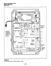
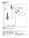
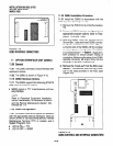
10.02 The QCNU is shown in Figure 4-7.
10.10 QCNU Configuration
10.11
The QCNU does not have to be configured
for operation.
10.20 QCNU Installation Procedure
10.21
Install the QCNU in accordance with the
following steps (Figure 4-7):
1) Remove the PCB from its protective packag-
ing.
2) Make sure that the power supply switch is
OFF.
3) Align and insert QCNU connectors
Jl
and J2
into motherboard connectors
J17
and
J18
respectively, and apply firm, even pressure to
ensure proper mating of connectors. (Note the
side with “+
RIGHT”
silkscreened on it
should be positioned as shown in Figure 4-7.)
10.30 QCNU Wiring
10.31
The QCNU does not require any wiring.
10.40 QCNU Programming Overview
10.41
The QCNU does not require any program-
ming.
4-15