


INSTALLATION-SIJE REQUIREMENTS
SECTION 100-816-202
MARCH 1993
1 GENERAL
1
.OO This chapter defines the installation site re-
quirements necessary to ensure a proper operat-
ing environment for the STRATA DK8 and DK16.
Also included are grounding requirements.
2 INPUT POWER REQUIREMENTS
2.00 The system requires an input power source
of 117VAC nominal (85VAC - 135VAC), 50/60 Hz,
15 amps. The AC outlet is recommended to be
dedicated and unswitched, with a solid third wire
ground (refer to Paragraph 4). This is to eliminate
interference from branch circuit motor noise or the
like, and to prevent accidental power-off.
2.01 To avoid accidental power turn-off, it is recom-
mended that an ON/OFF wall switch not be used on
this dedicated AC circuit.
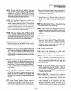
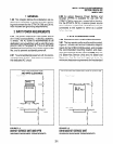
DK8 KEY SERVICE UNIT
AND HPFB CLEARANCE
FRONT VIEW
1
-42”+-10” 42”/4- 2”
Top*ALL
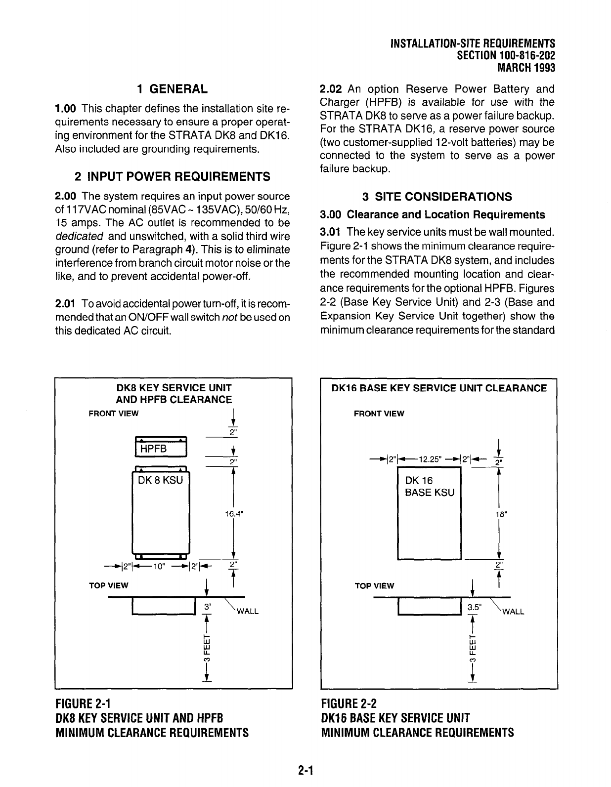
FIGURE 2-1
DK8 KEY SERVICE UNIT AND HPFB
MINIMUM CLEARANCE REQUIREMENTS
2.02 An option Reserve Power Battery and
Charger (HPFB) is available for use with the
STRATA DK8 to serve as a power failure backup.
For the STRATA DKl6, a reserve power source
(two customer-supplied 12-volt batteries) may be
connected to the system to serve as a power
failure backup.
3 SITE CONSIDERATIONS
3.00 Clearance and Location Requirements
3.01
The key service units must be wall mounted.
Figure 2-1 shows the minimum clearance require-
ments for the STRATA DK8 system, and includes
the recommended mounting location and clear-
ance requirements for the optional HPFB. Figures
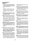
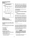
2-2 (Base Key Service Unit) and 2-3 (Base and
Expansion Key Service Unit together) show the
minimum clearance requirements for the standard
DK16 BASE KEY SERVICE UNIT CLEARANCE
FRONT VIEW
+2”+-12.25” 42”+-- -
TOP VIEW
1 f
,
I
WALL
L
FIGURE 2-2
DK16 BASE KEY SERVICE UNIT
MINIMUM CLEARANCE REQUIREMENTS
2-1