


INSTALLATION-PERIPHERALS
SECTION 100-816-207
MARCH 1993
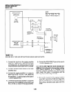
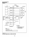
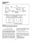
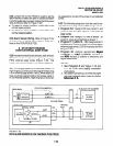
BASIC CONNECTION
3-pair
0825
Plug
Modular
DK8, QSMU*
DK16, PIOU
J
Cord (7 ft. max)
\
Printer
or Call
50 ft. max
*QSMU,
Jack
PROGRAM 1 O-3
Modularized
PPTClA-SM,
RS232, Modular
LED 04-OFF
to 0825 Adaptor
DATA FORMAT:
l
ASCII
l
g-bits
l
No parity
* 1 -stop bit
l
QSMU: 1200 bps
l
PlOWPIOUS 300 or
1200 bps
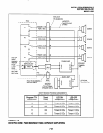
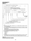
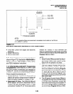
BASIC WIRING (see: QSMU PIOU or PIOUS TTY and SMDR Wiring in Chapter 8 for more detail)
PIOU, SMDR Jack
PPTCl A-5M Adaptor
RS-232
Modular Pin No. Modular Pin No. DB25 Pin No. Lead Name
1 To - 6 To - 3
RD
2 To - 5 To -
2 TD
3 To - 4 To -
6 DSR
4 To -
3 To - 20 DTR
5 To -
2 To - 8 CD
6 To -
1 To - 7 SG
4 Jumper to 5 RTS to CTS
FIGURE 7-20
DK8 AND DK16 PIOU/PIOUS SMDR CABLE CONNECTIONS
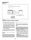
7 VOICE MAIL OPTIONS
7.00 System Hardware Requirements
7.01 The STRATA DK8 and DK16 may be config-
ured to support Toshiba VP voice mail messaging
system or a customer-supplier voice mail system.
7.02 The DK8 must be equipped with a QSTU, and
the DK16 must be equipped with a KSTU, PSTU, or
PESU to support a voice mail system. The DK8
QSTU is equipped with two standard telephone
circuits; the DK16 KSTU is equipped with four
standard telephone circuits, the PSTU with eight,
and the PESU with two. A K4RCU subassembly
must be installed in the DK16 Base Unit, and a
QRCU must be installed in the DK8 KSU. Thevoice
mail system can be connected to any standard
telephone circuit at the MDF block.
7.10 Toshiba VP Voice Messaging System
7.11 The STRATA DK8 and DK16 is designed to
support the full range of features offered by the
Toshiba VP provides various call routing, message
handling, and information management features,
including:
l
Automated Attendant
l
Call Forward to Voice Mailbox
l
Message Waiting Indication
7-28