


INSTALLATION-STATION APPARATUS
SECTION 100-816-206
MARCH 1993
NOTE:
DK8 and DK16 do not support the HDCB.
6.02 DK8 and DK16 systems can be equipped with
up to six MDFBs.
6.03 For DK8, DDCBs can only connect to Circuit
3 (Port 02) and Circuit 4 (Port 03).
6.04 For DK16, DDCBs can only connect to Ports
04 and 12. DDCBs can only connect to Circuit 5
(Port 04) of the Base Unit and/or Circuit 1 (Port 12)
of a PDKU or KCDU in the Expansion Unit.
NOTE:
DDCBs cannot connect to the QSTU, KSTU,
PSTU, PEW or PEKU.
6.10 DDCB and MDFB Cabling
6.11 Refer to Section 100-816-208 for DDCB and
MDFB wiring/interconnecting details. For door lock
control installation procedures, refer to Section
100-816-208. The length of the cable run from the
key service unit (KSU) to the MDFB (via the DDCB)
must not exceed 1,000 feet (305 meters), if using
24 AWG cable (see Table 8-D).
NOTES:
1. DDCB cable runs must not have the fol-
lo wing:
l
Cable splits (single or double)
l
Cable bridges (of any length)
l
High resistance or faulty cable splices
2. See Section 100-816-208 for secondary
protector information.
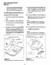
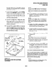
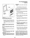
6.20 DDCB Wall Mounting
6.21 The DDCB is designed to be mounted on a
wall or other vertical surface. Mount the units in
accordance with the following steps:
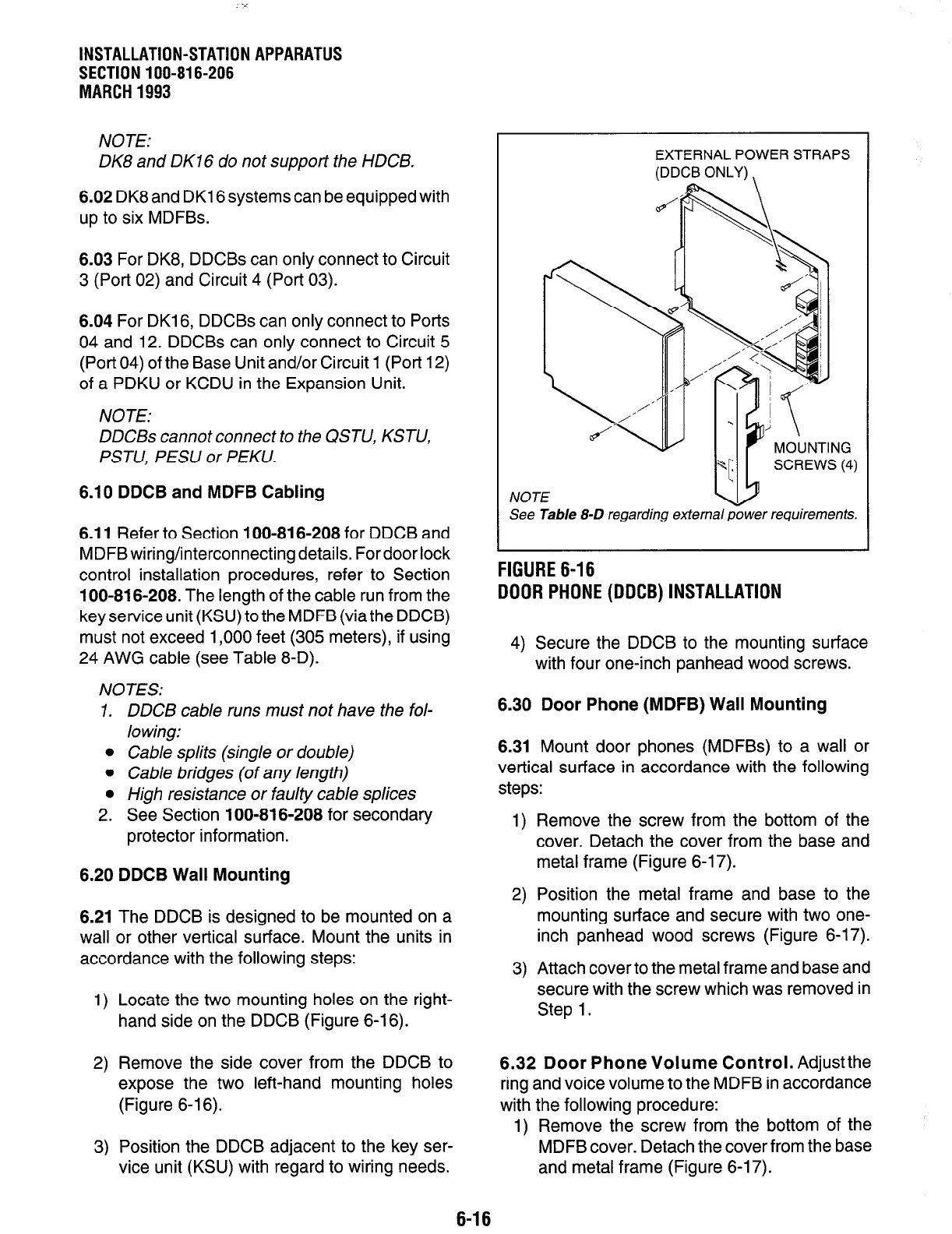
1) Locate the two mounting holes on the right-
hand side on the DDCB (Figure 6-16).
2) Remove the side cover from the DDCB to
expose the two left-hand mounting holes
(Figure 6-l 6).
3) Position the DDCB adjacent to the key ser-
vice unit (KSU) with regard to wiring needs.
EXTERNAL POWER STRAPS
(DDCB ONLY) \
NOTE
See Table 8-D regarding external power requlremenrs.
FIGURE 6-16
DOOR PHONE (DDCB) INSTALLATION
4) Secure the DDCB to the mounting surface
with four one-inch panhead wood screws.
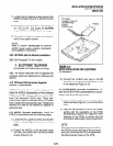
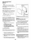
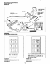
6.30 Door Phone (MDFB) Wall Mounting
6.31 Mount door phones (MDFBs) to a wall or
vertical surface in accordance with the following
steps:
1) Remove the screw from the bottom of the
cover. Detach the cover from the base and
metal frame (Figure 6-l 7).
2) Position the metal frame and base to the
mounting surface and secure with two one-
inch panhead wood screws (Figure 6-17).
3) Attach cover to the metal frame and base and
secure with the screw which was removed in
Step 1.
6.32 Door Phone Volume Control. Adjustthe
ring and voice volume to the MDFB in accordance
with the following procedure:
1) Remove the screw from the bottom of the
MDFB cover. Detach the cover from the base
and metal frame (Figure 6-17).
6-16