


INSTALLATION-PERIPHERALS
SECTION 100-816-207
MARCH 1993
b) Type
A
T H from the PC keyboard used
in step 5a.
l
PC 1 and PC 2 screens both display,
NO CARRIER.
l
The Data Call LEDs on each DKTare
Off.
XXX = PDIU-DI escape sequence (see
Paragraph 10.63)
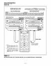
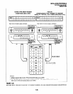
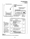
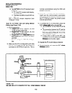
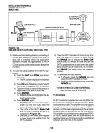
10.83 PC to Printer Test Call Using Manual
Dialing (see Figure 7-35)
1)
2)
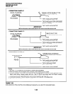
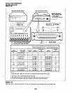
DIU Programming:
l
Program
20: Port 01. LEDs 01,02, and
17 ON; all other LEDs OFF.
l
Program
20: Port 03. LEDs 01,04, and
17 ON; all other LEDs OFF.
l
Program
39: Port 01. Data Call (56) and
Data Release (54) buttons should be
provided.
l
Default settings for PDIU-DI, S-Regis-
ters.
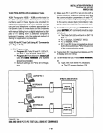
Make sure the PC is configured to print data
from its serial COM
port
(the PC COM
port
normally accomplished using the DOS and
MODE commands.
3) Using the manufacturer’s documentation,
make sure the communication parameters
(data speed, parity, data bits, stop bits, etc.) of
the PC COM port match the printer’s serial
interface parameters.
4) To connect the PC to the printer, press the
DKT’s Data Call button and dial 1 3.
l
The CONNECT on the PDIU-DS will be
lit.
l
The connection between the PC and the
printer is completed, as shown by the
thick lines above (PDIU-DS 13 is in the
communication mode).
l
If busy tone is sent to the DKT, the
connection is not complete; press Data
Release and try step 4 again.
5) Operate the PC to print data as required.
6) To terminate the call, press the DKT’s Data
connected to DKT/PDIU-DI port 01). This is
Release button.
RS-23:
6
2
RS-232
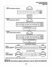
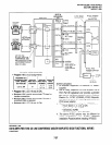
FIGURE 7-35
DK8 AND DK16 PC TO PRINTER TEST CALL USING MANUAL DIALING
7-52