


INSTALLATION-PERIPHERALS
SECTION lOO-816-207
MARCH1993
l
LED
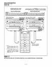
06: Should be ON for DlUs con-
nected to modems. With this feature
turned on, the DIU will send a one-sec-
ond release signal on the DTR to drop the
modem when the data user presses the
Data Release button on the telephone.
l
LEDs 17
- 20: Data security groups can
be used to allow or deny digital telephones
equipped with PDIU-Dls access to the
PDIU-DS ports connected to a modem.
DIU stations can only make data calls to
DlUs in the same data security group.
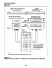
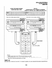
Program 21
l
For each PDIU-DS/modem pair, assign
the digital, QSTU, KSTU, and PSTU (or
PESU) ports that will be connected to the
PDIU-DS and modem, respectively.
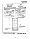
Program 22/33
l
If more than one modem/PDIU-DS pair is
configured as a system modem pool, the
PDIU-DSs should be set to hunt each
other in
Program
22. The modem QSTU,
PSTU, KSTU, or PESU ports should be
set to hunt each other in
Program 33.
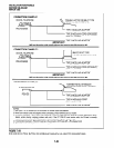
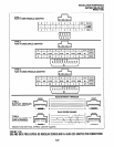
Program 31
l
LED 18 should be turned on for all QSTU,
KSTU, PESU or PSTU station ports that
are connected to modems. This provides
data security by preventing executive or
privacy override of modem calls.
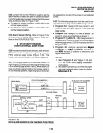
10.63 Modem Setup Recommendations
1) Always change the escape sequence of the
telephone PDIU-DI from default (+++) tosome
other ASCII character (ATS2=XX command
to PDIU-DI). This allows placing the PDIU-DI
or modem into the command mode selec-
tively. The ATS2=XX command should be in
the modem initialization command of the com-
munication software of the PC connected to
the PDIU-DI (XX = new ASCII Escape char-
acter). This will ensure that the new Escape
sequence is restored if the telephone or
PDIU-DI is unplugged.
2) Set the modem to recognize the DTR signal to
disconnect (AT&D2 command to modem).
3) When the modem tracks the DCD signal,
issue AT&Cl command to modem.
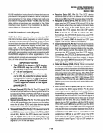
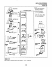
10.70 PDIU-DS Disassembly and Assembly
10.71
To set the jumper plugs
(Pl - P9)
on the PCB
inside the PDIU-DS for DCE or DTE operation, the
PDIU-DS must be disassembled. Disassemble
the PDIU-DS in accordance with the following
steps:
10.72 Disassembling the PDIU-DS
1) Remove the four screws securing the bottom
panel to the rest of the unit (see Figure 7-33).
These screws are not captive; so place to-
gether where they can be easily accessed.
2) Remove the bottom panel.
3) Remove the PCB inside the PDIU-DS by
lifting the back panel from its side grooves.
4) Turn the PCB over and set the jumper plugs
(Pl
-
P9)
as follows:
l
If the PDIU-DS is connected to a DTE,
set the plugs to the “A-B” position.
l
If the PDIU-DS is connected to a DCE de-
vice, set the plugs to the “B-C” position.
NOTE:
Do not cut PDIU-DS PERCEPTION jumper
wire for STRATA DK8 or DK16 installations.
10.73 Assembling the PDIU-DS
1) Position the back panel to the PCB (see Fig-
ure 7-33).
2) Slide the back panel down into its side grooves.
3) Attach the bottom panel, and secure with the
four non-captive screws.
7-40