


INSTALLATION-WIRING DIAGRAMS
SECTION lOO-816208
MARCH1993
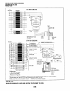
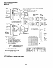
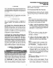
DB-25 RS-232
WALE) \
PDIU-DS,
TO ASCII
TERMINAL,
OR
EXTERNAL
MODEM
l
7-BIT
l
EVEN PARITY
l
I-STOP BIT
DB-25 RS-232
(MALE) \r
TO PRINTER
PDIU-DS,
OR CALL
ACCOUNTING
DEVICE
l
&BIT
. NO PARITY
l
l-STOP BIT
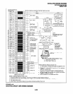
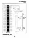
NOTE 1:
If connected to an external Hayes compatible modem, interchange pin 2
and pin 3, and pin 20 and 8. Send AT&Cl 80250 = 6A W <ENTER>
command to external modem
OTE 2: Wire colors may vary with other
types of modular adaptors.
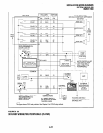
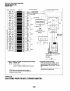
MAINTENANCE
PIOU
PORT
\
CARD 4
ADAPTOR PART NO. PPTC
\TYRD -,’
STATION MESSAGE
DETAIL RECORDING
PORT
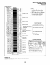
NOTE 3: PIOLJ option settings:
SW1 - Sets the SMDR baud rate
to be 300 or 1200 BPS.
PIOU MODULAR PIN-OUT
S W2 - Sets the PlOlJ programming speed to be
300 or 1200 BPS (for IMDU or 77-Y jack).
LED CO4 “On” = 300 BPS/S W2 set “In”.
LED CO4 “Off’= 1200 BPS/SW2 set “Out”.
S W3 - Sets the PlOU to operate with the
IMDU or an external device
connected to the TTY modular jack.
MO&I
- For IMDU operation (7, even, 1)
TV ~~~~
- For ASCII terminal (8, none, 1)
or external modem (8, none, 1).
P13 - Sets the IMDlJ and Tp/ jack
for bell or CC/m specification.
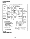
PPTC PIN-OUT
SEE
PIOU/MDF
DRAWING
IN THIS
SECTION
NOTE 4: PDIlJ-DS jumpers should be set to
the B-C position when connected t
o the PlOU ll?’ or SMDR port.
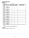
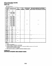
LEAD NAME TD RD JUMPER DSR SG CD DTR
DB25 PINS 2 3 4-5 6 7
8 20
MODULAR PINS 5 6 N/A 4 1 2 3
WIRECOLOR Y W BR G BL BK R
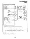
TTY
(6-PIN
MODULAR
JACK)
SMDR
(6-PIN
MODULAR
JACK)
- SW2
-LED
CD4
(25-PAIR
FEMALE
AMP.
JACK)
FIGURE 8-26
DK16 PIOU SMDR/TTY OPTIONS AND WIRING
8-30