INSTALLATION-PERIPHERALS
SECTION 100-816-207
MARCH 1993
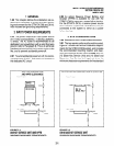
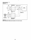
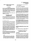
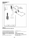
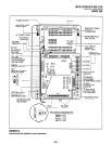
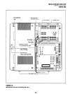
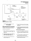
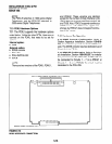
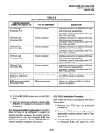
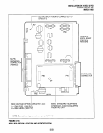
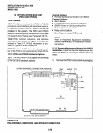
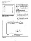
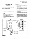
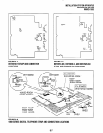
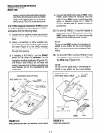
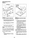
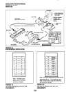
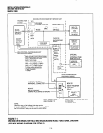
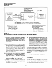
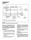
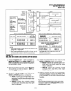
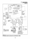
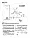
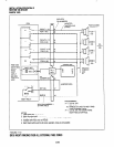
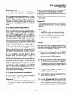
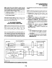
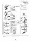
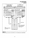
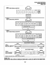
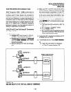
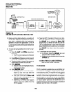
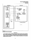
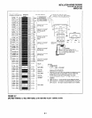
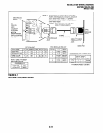
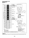
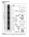
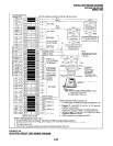
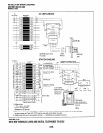
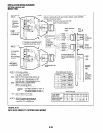
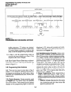
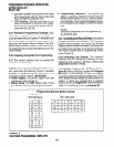
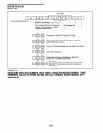
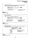
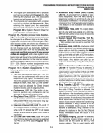
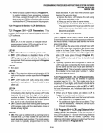
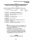
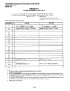
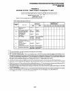
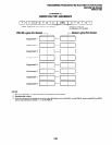
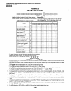
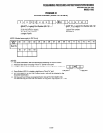
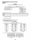
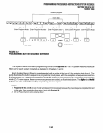
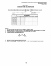
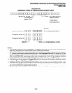
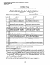
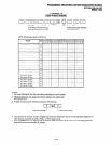
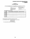
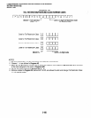
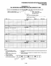
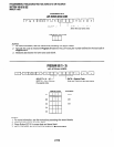
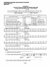
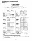
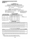
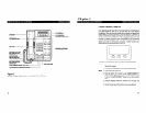
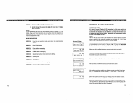
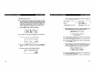
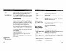
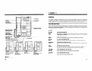
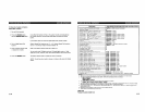
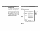
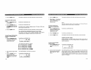
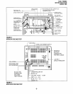
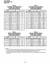
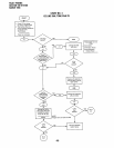
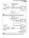
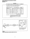
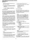
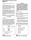
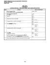
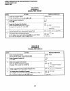
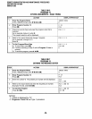
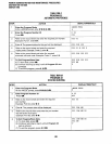
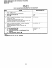
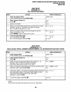
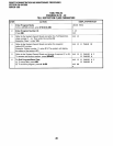
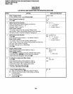
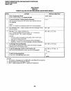
4.23 Amplified Speaker Installation.
install the
HESB Amplified Speaker option in accordance
with
1)
2)
3)
4)
5)
6)
7)
8)
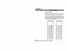
the following steps (refer to Figure 7-12):
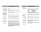
Connect a jumper between terminals 1 and 2
of the HESB
TBl
terminal block.
Connect a jumper between terminals 6 and 7
of the HESB
TBl
terminal block.
Connect a jumper between terminals 5 and 8
of the HESB
TBl
terminal block.
Connect a jumper between terminals 3 and 4
of the HESB
TB2
terminal block.
Connect a jumper between terminals 5 and 6
of the HESB
TB2
terminal block.
Connect the 600 ohm PAGE RCA jack output
on the DK8 KSU or DK16 Base Unit to termi-
nals 3 and 4 of the HESB TBl terminal block.
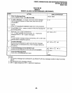
Connect the power supply’s +I 2V lead to ter-
minal 1 of the HESB
TB2
terminal block, and
connect the
OV
lead to terminal 2.
Plug the provided power cord into the power
supply and to a 117VAC, 60Hz power source.
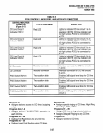
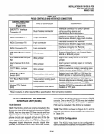
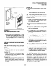
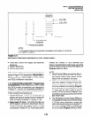
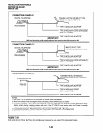
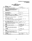
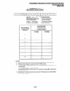
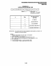
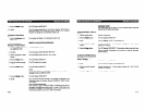
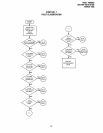
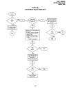
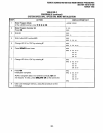
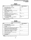
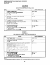
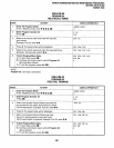
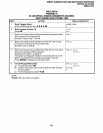
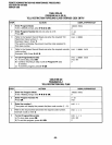
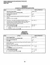
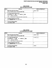
4.24 Amplified Speaker Test.
Test the amplified
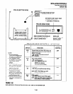
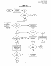
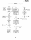
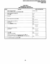
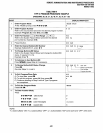
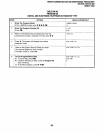
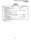
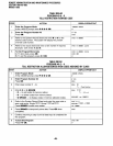
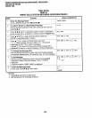
4.26 Talkback Amplified Speaker Test.
Test the
speaker installation in accordance with the follow-
Talkback Amplified Speaker installation in accor-
ing steps:
dance with the following steps:
1) Make an external page.
l
Page should be heard over the HESB.
2) Adjust the HESB volume control to the desired
level (screwdriver adjustment on back of
HESB).
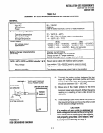
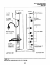
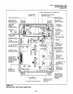
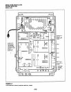
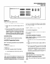
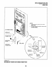
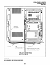
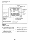
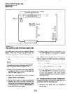
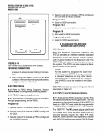
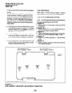
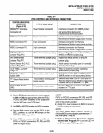
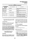
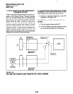
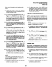
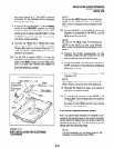
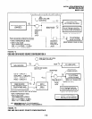
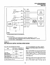
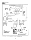
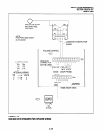
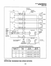
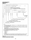
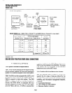
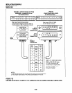
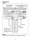
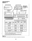
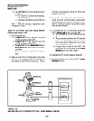
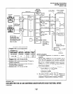
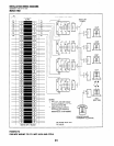
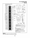
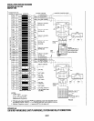
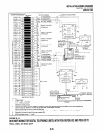
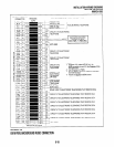
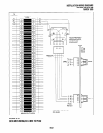
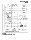
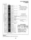
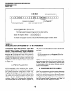
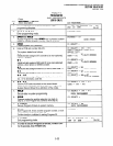
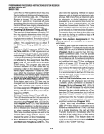
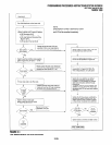
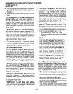
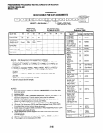
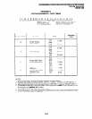
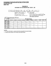
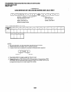
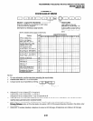
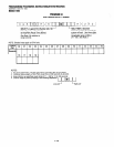
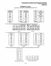
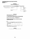
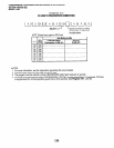
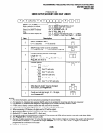
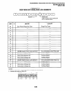
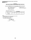
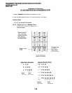
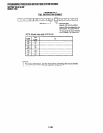
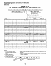
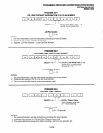
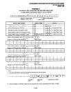
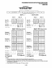
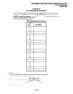
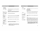
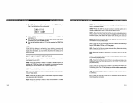
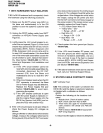
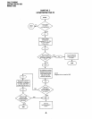
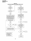
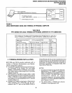
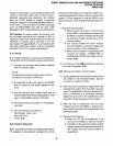
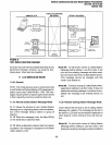
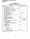
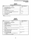
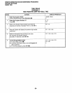
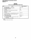
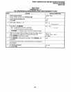
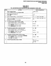
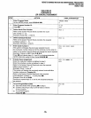
4.25 HESB/MDFB Talkback Amplified Speaker
Installation.
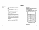
Install the HESB/MDFB Talkback
Amplified Speaker option in accordance with the
following steps (refer to Figure 7-13):
1) Connect a jumper between terminals 1 and 2
of the HESB
TBl
terminal block.
2) Connect a jumper between terminals 3 and 4
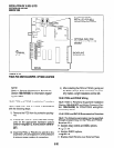
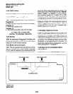
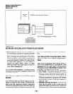
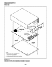
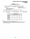
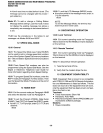
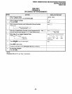
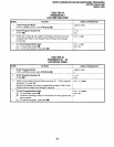
1) Find a suitable location on the mounting sur-
of the HESB
TB2
terminal block.
face for the HESB.
3) Connect a jumper between terminals 5 and 6
of the HESB
TB2
terminal block.
NOTE:
HESB connections made in steps 4 - 7 may
be accomplished using the HESB VOICE and
DOOR PHONE modular jack instead of the
TB1 terminal block.
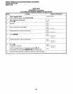
4)
5)
6)
7)
8)
9)
10)
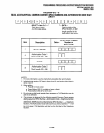
Connect terminal 7 of the HESB
TBI
terminal
block to pin Ll of the MDFB.
Connect terminal 8 of the HESB
TBI
terminal
block to pin L2 of the MDFB.
Connect terminal 9 of the HESB
TBl
terminal
block to pin 1 of the MDFB.
Connect terminal 10 of the HESB
TBl
termi-
nal block to pin 2 of the MDFB.
Connect the 600 ohm PAGE RCA jack output
from DK8 KSU or DK16 base unit to terminals
3 and 4 of the HESB TBl terminal block.
Connect the HACU-120 Power Supply’s
+12V
lead to terminal 1 of the HESB
TB2
terminal
block, and connect the
OV
lead to terminal 2.
Plug the provided power cord into the power
supply and to a 117 VAC, 60Hz power source.
1)
2)
Make an external page.
l
Page will be heard over the HESB.
Verify that someone speaking into the door
phone can be heard at the paging station (with
this application, pressing the door phone but-
ton is not required to talkback through the door
phone).
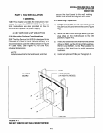
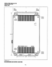
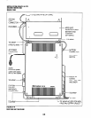
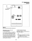
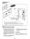
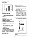
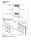
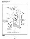
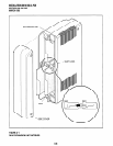
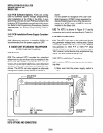
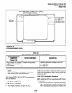
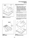
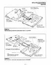
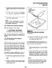
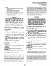
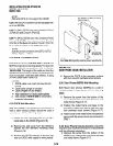
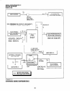
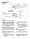
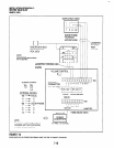
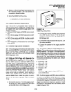
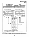
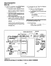
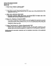
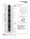
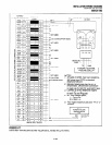
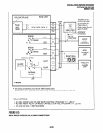
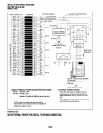
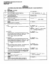
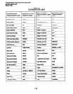
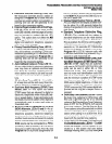
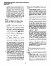
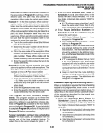
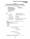
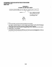
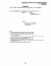
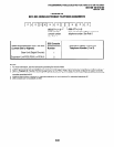
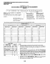
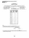
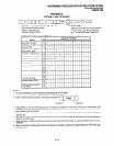
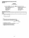
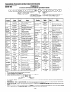
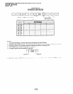
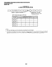
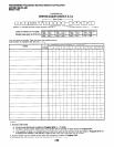
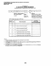
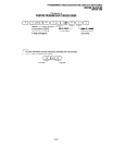
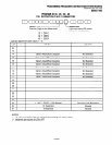
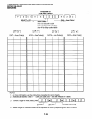
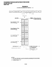
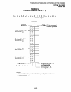
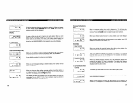
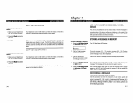
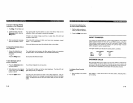
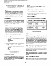
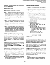
4.27 HESB Wall Mounting Instructions.
The
HESB can be mounted to a wall or other vertical
surface. Use the following instruction to mount the
HESB (see Figure 7-14).
7-16