


INSTALLATION-DK 16 KSU & PCB
SECTION 100-816-205
MARCH 1993
5.33 PCB Software Options. PCBs are config-
ured for software options through programming,
after installation of the PCBs in the KSU. A pro-
gramming overview for each PCB is provided in the
individual PCB installation procedures in this chap-
ter. Referto the Programming Procedures, Section
100-816-300, for detailed programming instruc-
tions.
5.40 PCB Installation/Power Supply Consider-
ations
5.41 Whenever removing or installing PCBs it is
recommended that the power supply be OFF.
6 BASE UNIT STANDARD TELEPHONE
INTERFACE UNIT (KSTU)
6.00 General
6.01 The optional KSTU provides four standard
telephone circuits and it can only be installed in the
Base Unit. The KSTU supports the two-wire de-
vices such as standard telephones, Auto Attendant
devices, voice mail machines, and facsimile ma-
chines. The KSTU can also support an alternate
NOTE:
For the system to recognize the Dual-Tone
Multi-Frequency (DTMF) tones generated by
standard telephones (oranyotherdevice con-
nected to a KSTU port), a K4RCU must be
installed in the Base Unit.
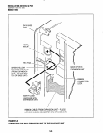
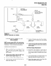
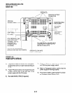
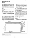
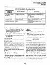
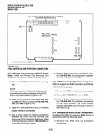
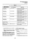
6.02 The KSTU is shown in Figure 5-l 1 and its
connectors and controls are described in Table 5-A.
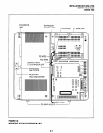
6.10 KSTU Configuration
6.11 The KSTU only has to be configured for the
ring generator voltage level, nothing else. Before
installing the KSTU in the Base Unit, set the SW540
ring generator to 130V P-P or 19OV P-P. Most
standard telephones and two-wire devices require
190; however, some devices may experience ring-
trip at 190, and should be set at 130.
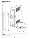
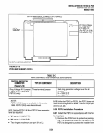
6.20 KSTU Installation Procedure
6.21 Install the KSTU in accordance with the follow-
ing steps:
1) Make sure that the power supply switch is
Background Music (BGM) source on circuit 4. OFF.
FIGURE 5-11
KSTUOPTIONSANDCONNECTORS
5-14