


INSTALLATION-DK8 KSU & PCB
SECTION 100-816-204
MARCH 1993
7.40 QCDU Programming Overview
7.41 The following parameters may be specified,
through programming, for the QCDU.
Program 1 O-l
l
Allows/denies two-CO Line Conference and Di-
rect Inward System Access (DISA).
Program 15
l
Auto Release detection; DISA, and other at-
tributes to the CO line.
Program 16
l
Assigns CO line to groups 81 - 84, and dial 9
group.
Program 40
l
Assigns stations access to CO line (incoming
and outgoing access).
8 STANDARD TELEPHONE
INTERFACE UNIT (QSTU)
8.00 General
8.01
The QSTU provides two standard telephone
circuits. The QSTU supports two-wire devices such
as standard telephones, Auto Attendant devices,
separate BGM source connection, voice mail ma-
chines, and facsimile machines.
NOTE:
For the system to recognize the Dual-Tone
Multi-Frequency (DTMF) tones generated by
standard telephones (orany other device con-
nected to a QSTU port), a QRCU must be
installed.
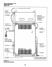
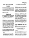
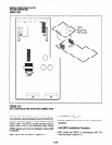
8.02 The QSTU is shown in Figure 4-10. Note that
the QSTS PCB is factory installed on the QSTU.
8.10 QSTU Configuration
8.11
The QSTU only has to be configured for the
ring generator voltage level, nothing else. Before
installing the QSTU in the KSU, set the
SW1
ring
generator to 13OV P-P or 19OV P-P (Figure 4-10).
Most standard telephones and two-wire devices
require 190; however, some devices may experi-
ence ring-trip at 190, and should be set at 130.
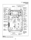
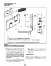
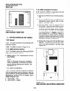
8.20 QSTU Installation Procedure
8.21 Install the QSTU in accordance with the fol-
lowing steps (Figure 4-7):
1) Remove the PCB from its protective packag-
ing.
2) Set the ring voltage jumper plug
SW1
to select
the appropriate ring generator voltage level,
either 130V P-P or 19OV P-P.
3) Make sure that the power supply switch is
OFF.
4) Align and insert QSTU connectors
Jl, J2, J3,
and 54 motherboard connectors
Jll, J12,
J13,
and
J14
respectively, and apply firm, even
pressure to ensure proper mating of the con-
nectors.
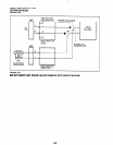
8.30 QSTU Wiring
8.31 Referto DK8 MDF to KSU Amphenol Wiring in
Section 100-816-208 for QSTU wiring.
8.32 The QSTU must be connected to a OL13A (or
equivalent) type lines for off-premises stations.
(300 ohms loop resistance max., including the
telephone or other devices DC off hook resistance.)
8.40 QSTU Programming Overview
8.41 The following parameters may be specified for
the QSTU:
Program 31
l
Used to configure all QSTU ports connected to voice
mail (see Chapter 7 for voice mail installation).
Program 1 O-2
l
Used to set standard telephone ringing option
and separate BGM assignment.
NOTE:
QSTU Ports are fixed. They are assigned
even if a QSTU is not installed.
9 DTMF RECEIVEWABR TONE
DETECTOR UNIT (QRCU)
9.00 General
9.01
The QRCU must be installed to recognize
Dual-Tone Multi-Frequency (DTMF) tones gener-
4-13