


1 GENERAL
1.01
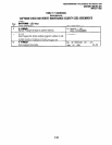
This chapter consists of System Record
Sheets and instructions on how to fill out each of
them. The chapter begins with the instructions:
first the basic program instructions, then the Toll
Restriction instructions, and then the Least Cost
Routing instructions. The remainder of the chapter
contains the System Record Sheets, organized in
the same sequence as the instructions.
1.10 Record Sheet Data Entry
1.11
The System Record Sheets are used to
record the assignment of features or operation of
each program. The following descriptions and
considerations of the available programming
choices will be helpful when filling out the record
sheets.
1 .I2 Initialized data information can be found in
the Notes at the bottom of each System Record
Sheet.
1.20 Logical Ports and Physical Ports
1.21
There are two types of ports in the STRATA
DK8/DK16 systems. This distinction gives cus-
tomers greater mobility in relocating their stations.
Physical ports can be defined as the actual hard-
ware-printed circuit board (PCB) circuit, wiring,
and jack (RJl 1) that stations plug into-that is
connected to the system. Logical ports are at-
tributes associated with a station (telephone)-
station number, personal Speed Dial numbers,
and the complement of features assigned to the
station in system software programs. A Logical
port always is associated with a physical port.
1.22
Physical ports can be considered as fixed;
they cannot be moved. Logical ports, though, are
not fixed. They can be moved from one physical
port to another physical port. It is important to note
that logical ports can only be moved to related
physical ports: Digital logical port (telephone) to
digital physical port (QCDU and KSU digital cir-
cuits for STRATA DK8; PDKU, KCDU, and the
Base Unit digital circuits for STRATA DK16),
electronic logical port (telephone) to electronic
physical port (PEKU and PESU for STRATA DKI 6),
and standard logical port (standard telephone) to
standard physical port (QSTU for STRATA DK8;
PSTU, PESU, and KSTU for STRATA DK16).
SkCTlON 100-816-302
MARCH 1993
When entering ports into program data, except for
Program 01,
always enter the logical port number.
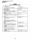
1.30 Basic System Record Instructions
Program 90-Initializing Programs:
All cus-
tomer data can be cleared and set to the initial-
ized state for any program or range of programs.
If the system is being installed for the first time
or if installing a KFCU in a STRATA DK16 (if
instructions specify), this program must be run
to erase random data from RAM. Initialized data
information can be found at the bottom of each
program System Record Sheet. If the system is
being installed for the first time or in a new
location or when installing a KFCU in a STRATA
DK16 (if instructions specify), all programs (00 -
97) should be initialized.
Program 92-Initializing Speed Dial Numbers,
Voice Mail ID Codes, Character Message
Memory, Timed Reminders, Call Forward,
and Digital Telephone Volume Levels:
All
previously entered or random data (of the type
listed) is cleared by this program. This program
must be run when installing a system for the first
time or in a new location or when installing a
KFCU in a STRATA DK16 (if instructions specify).
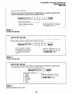
NOTE:
Program 03
applies to STRATA DK16 only.
Program 03-DK16 Flexible PCB Slot Assign-
ments:
This program is used to tell the system’s
software how the system is configured. The
configuration is based on slots, and the system
must know what is in each slot. Enter a new code
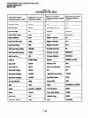
or verify the default code for each slot. (See the
PCB Code Reference Table on the
Program 03
System Record Sheet.) This Program must be
run if the system is being installed for the first
time, or when adding a new PCB, or when
installing a KFCU (if instructions specify).
For this program’s purpose, the Base Key
Service Unit is divided into four fixed slots, even
though the unit has no slots per se. Slot 00
represents the system’s common control (CTU);
Slot 01 the Base Unit’s eight digital circuits/ports
(DKU); Slot 02 the Base Unit’s four CO line
circuits (KCOU); and Slot 03 the optional KSTU
PCB in the Base Unit.
The optional Expansion Unit has four slots
(04 - 07). Unlike the Base Unit, the Expansion
Unit’s slots are universal. This means that each
2-1