


INSTALLATION-STATION APPARATUS
SECTION lOO-816-206
MARCH1993
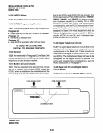
To accommodate the digital telephone line cord,
the cable should be terminated in a modular sta-
tion connector block (RJ-11) at the station location.
The standard single-pair, modular digital telephone
cord that is sent with the telephone is 7 feet (the
maximum allowed is 25 feet).
NOTES:
1. Digital telephone cable runs must not
have the following:
l
Cable splits (single or double)
l
Cable bridges (of any length)
l
High resistance or faulty cable splices
2. See Section 100-816-208 for secondary
protector information.
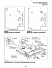
2.20 Connecting Electronic Telephones to
the System (DK16 only)
2.21 The following provides information on how to
connect electronic telephones to the DK16 system.
NOTE:
Before proceeding, see warning and caution
notes in Paragraph 2.01.
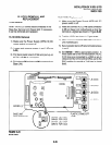
2.22 Electronic telephones are connected to
electronic telephone circuits in the DK16 Expan-
sion Unit on the Electronic Telephone Interface
Unit (PEKU) and the Standard/Electronic Tele-
phone Interface Unit (PESU) via the main distribu-
tion frame (MDF) with standard twisted-pair jack-
eted telephone cable. Two-pair wiring, as a
minimum, is required for telephone connection.
However, three-pair wiring is recommended to
permit future upgrades, such as Off-hook Call
Announce.
To accommodate the electronic telephone line
cord, the cable should be terminated in a modular
station connector block (RJ-11) at the station lo-
cation. The standard two-pair modular electronic
telephone cord length is seven feet (the maximum
allowed length is 25 feet). See Wiring diagrams,
Section 100-816-208 for more details.
NOTE:
See Section 100-816-208 for secondarypro-
tector information.
The overall iength of the station cable run from the
DK16 key service unit (KSU) to the telephone must
not exceed 1,000 feet (305 meters), if using 24
AWG cable.
2.30 Connecting Standard Telephones to the
System
2.31 The following provides information on how to
connect standard telephones to the DK8 or DK16
system.
NOTE:
Before proceeding, see warning and caution
notes in Paragraph 2.01.
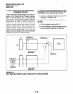
2.32 Standard telephones connect to standard
telephone circuits in the DK8 Standard Telephone
Interface Unit (QSTU), telephone circuits on the
DK16 Base Unit Standard Telephone Inter-face
Unit (KSTU), the DK16 Standard Telephone Inter-
face Unit (PSTU), and the DK16 Standard/Elec-
tronic Telephone Interface Unit (PESU) via the
main distribution frame (MDF) with standard
twisted-pair jacketed telephone cable. Single-pair
wiring is required. (Refer to Wiring Diagrams,
Section 100-816-208, for more details.)
NOTE:
See Section 100-816-208 for secondary
protector information.
The standard telephone cable’s overall loop re-
sistance, connected on- or off-premises, is 300
ohms maximum, including the telephone resis-
tance. This also applies to all devices connected to
standard telephone circuits. A standard telephone
connected off-premises via the telephone network
should interface with OL13A lines (or equivalent)
and connect to an RJ21 X FIC jack (or equivalent).
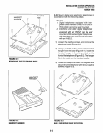
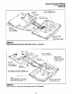
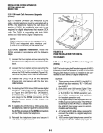
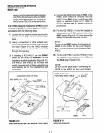
2.40 Telephone Wall Mounting
2.41 This section provides instructions on how to
mount digital telephones and electronic telephones
(DK16 only) to a wall or other vertical surface.
Instructions on mounting standard telephones are
not provided here; refer to the manufacturer’s
documentation for those instructions.
6-2