


INSTALLATION-STATION APPARATUS
SECTION 100-816-206
MARCH 1993
NOTE:
1. DDSS console cable runs must not have
the folio wing:
l
Cable splits (single or double)
l
Cable bridges (of any length)
l
High resistance or faulty cable splices
2. See Section 100-816-208 for secondary
protection information.
CAUTION!
When installing the DDSS cable, do not
run parallel to and within 3 feet of an AC
power line. AC power lines should be
crossed at right (90”) angles only. In par-
ticular, avoid running station wire pairs
near devices that generate electricalnoise,
such as neon or fluorescent light fixtures.
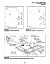
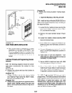
5.12 DDSS Console Configuration. The follow-
ing considerations should be made when installing
DDSS consoles:
DDSS consoles can connect only to Circuit 8 of
the Base Unit digital telephone circuit set or
Circuit 8 of the PDKU.
A maximum of two DDSS consoles can be
installed per system equipped with an Expan-
sion Unit.
DDSS consoles can operate with an attendant
electronic telephone, as well as with a digital
one.
A KCDU will not support a DDSS.
5.13 DDSS Programming Overview
Program 03
l
Code 64 identifies the slots that support DDSS
consoles.
Program 28
l
Assigns DDSS console(s) to telephones.
Program 29
l
Assigns button functions for DDSS consoles.
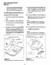
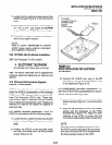
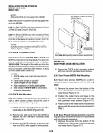
5.20 HDSS Console Connections
5.21
The HDSS console must be connected to the
data pairs of circuits 7 and 8 on a PEKU in the
Expansion Unit (via the MDF) with standard two-
pair twisted, jacketed telephone cable. To accom-
modate the connection, the instrument end of the
HDSS console cable should be terminated in a
modular station connector block @J-11). Refer to
Wiring Diagrams, Section 100-816-208, for wiring/
interconnecting details. The overall length of the
cable run from the Expansion Unit (KSU) to the
HDSS console must not exceed 500 feet (152
meters), if using 24 AWG cable. The HDSS con-
sole can operate with either an electronic or digital
telephone (preferably an LCD model).
CAUTION!
When installing the HDSS console cable,
do not run parallel to and within 3 feet of an
AC power line. AC power lines should be
crossed at right (90”) angles only. Avoid
running HDSS console wire pairs near
devices thatgenerate electricalnoise, such
as neon or fluorescent light fixtures.
5.22 HDSS Console Configuration. The fol-
lowing considerations should be made when in-
stalling an HDSS console:
A PEKU PCB is required in the expansion unit
for an HDSS console. (The DSS switch on the
PEKU must be set to DSS.)
Two PEKU ports are required for the HDSS
console (always Circuits 7 and 8).
The PESU does not support the HDSS console.
A system must be configured with the Expan-
sion Unit to support an HDSS cohsole. Only one
HDSS console can be installed in a system.
5.23 HDSS Programming Overview
Program 03
l
Codes 23 and 24 identify the slot that supports
a PEKU that interfaces with the HDSS console.
Program 28
l
Assigns HDSS console to a telephone.
Program 29
l
Assigns individual button functionsforthe HDSS
console.
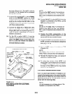
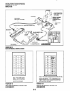
6 DOOR PHONE/LOCK CONTROL UNIT
AND DOOR PHONE INSTALLATION
6.01 This section provides installation instructions
forthedigitaldoorphone/lockcontrolunits(DDCB).
It also includes installation instructions for the door
phone (MDFB). Each DDCB can support as many
as three door phones (MDFBs), or two MDFBs and
one door lock.
6-15