


INSTALLATION-PERIPHERALS
SECTION 100-816-207
MARCH1993
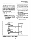
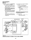
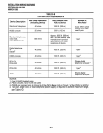
11.02 Amplified Talk PathiFigure 7-39 provides a
functional diagram of a two-CO line amplified con-
ference connection (an R-TEC VFR5050 amplifier
is used here). The talk path for the connection is as
follows: outside party l-public telephone net-
work-CO, CKTX-STRATA DK16-PEKU, port
A-into AMP, CKTA-Out AMP, CKT B-PEKU,
port B-STRATA DKI 6-CO, CKTY-public tele-
phone network-outside party 2. This path is two-
way so when outside party 2 talks, the talk level is
amplified in the reverse direction.
NOTE:
Only the outside party 1 talk path is amplified
to/from a system telephone when it is con-
nected into a two-CO line conference.
11.03 Amplifier Requirements.
l
Customer-supplied.
l
Must be FCC-registered, Part 68, and
provide automatic gain control.
l
Requires two PEKU or PESU station
ports (17 and 18).
l
Refer to the amplifier manufacturer’s in-
stallation documentation for amplifier
grounding instructions.
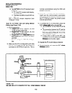
11.04 Installation. Connect a two-way amplifier to
the STRATA DK16 system in accordance with the
following steps (see Figures 7-39 and 8-27).
1) At the main distribution frame (MDF), connect
the voice pair (VT, VR, port A) of circuit 6 on
the designated PEKU or PESU PCB to one
input of the customer-supplied two-way am-
plifier. In the example in Figure 7-39, this is
CKTA (Central Office Side A) of the VFR5050.
2) At the MDF, connect the voice pair (VT, VR,
port B) of circuit 7 on the designated PESU or
PEKU PCB to the other input of the amplifier.
In the Figure 7-39 example, this is CKTB
(subscriber side B) of VFR5050.
3) Plug the amplifier’s power cord into the 117
VAC (standard) wall outlet.
4) Set the gain and other amplifier parameters
options per the amplifier manufacturer’s in-
stallation documentation.
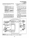
5) Program the STRATA DK16 system as
follows:
l
Program 1 O-3: Enables the appropriate
PEKU or PESU PCB ports for amplifier
connection. Only enable the ports that
will be connected with the amplifier(s).
l
Program 15-5: Enables appropriate CO
lines for tandem connection.
l
Program 1 O-l : LEDs 19 and 20 must be
ON.
l
Program 1 O-2: LED 18 and 19 must be
ON.
7-58