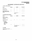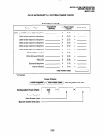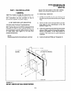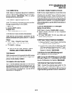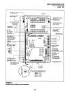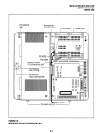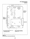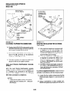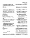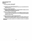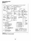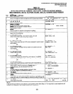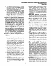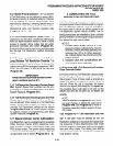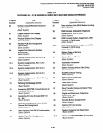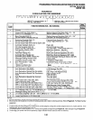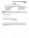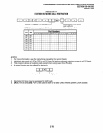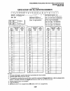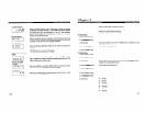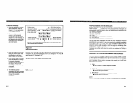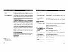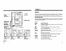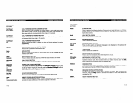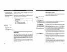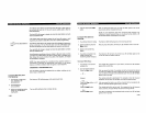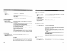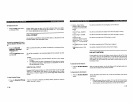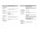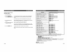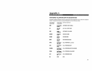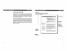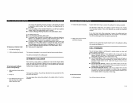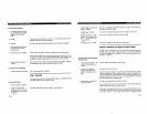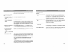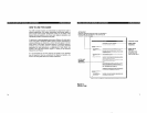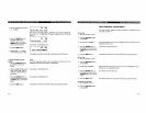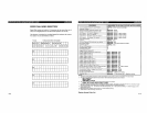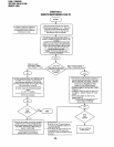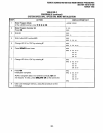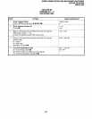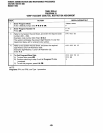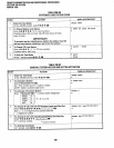
INSTALLATION-WIRING DIAGRAMS
SECTION lOO-816-208
MARCH1993
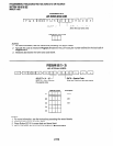
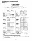
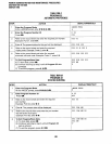
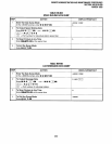
PDIU-DS,
TO ASCII
1
1
D
TOSHIBA W-23
-,,,/- SMSG
rr SMCD 6
-SMDTR-
3
- .shrln.sR -
1
TO PRINTER
/
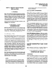
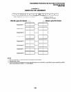
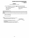
STATION MESSAGE
DETAIL RECORDING
PORT
l-l-Y
(IMDU)
(6-PIN
MODULAR
JACK)
DB-25 RS-232
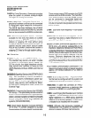
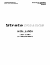
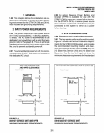
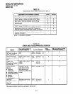
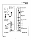
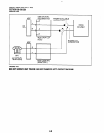
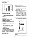
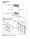
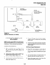
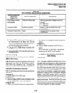
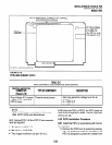
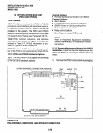
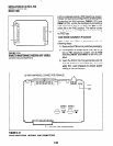
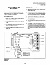
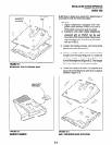
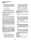
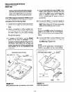
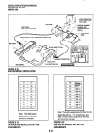
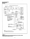
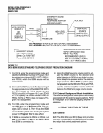
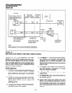
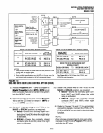
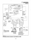
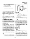
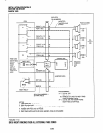
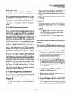
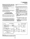
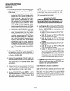
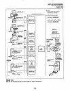
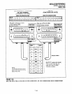
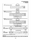
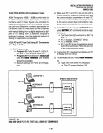
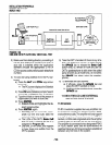
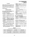
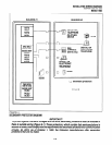
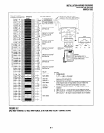
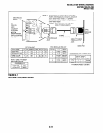
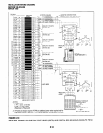
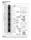
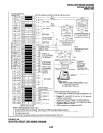
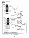
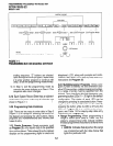
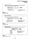
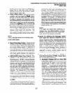
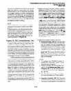
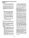
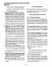
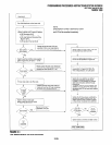
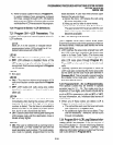
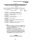
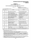
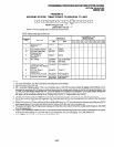
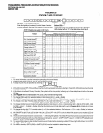
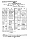
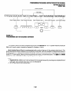
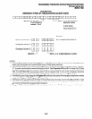
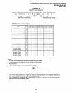
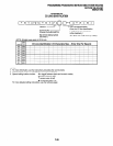
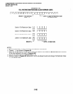
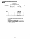
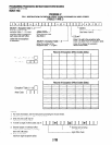
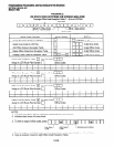
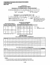
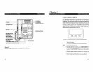
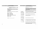
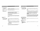
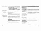
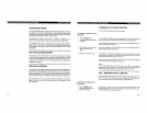
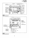
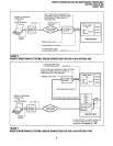
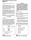
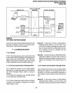
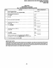
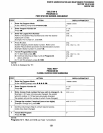
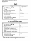
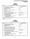
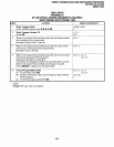
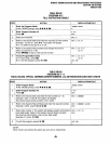
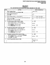
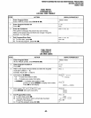
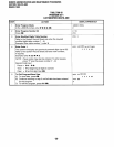
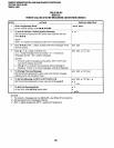
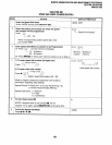
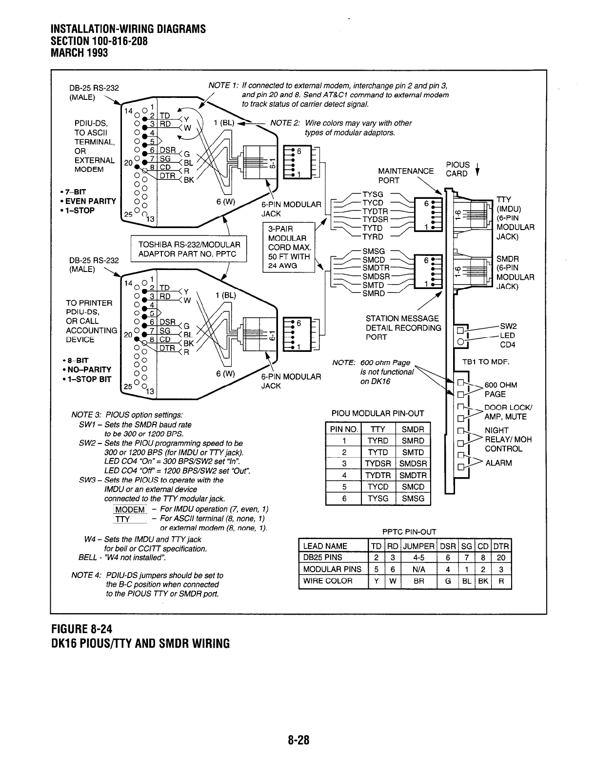
NOTE 1: If connected to external modem, interchange pin 2 and pin 3,
and pin 20 and 8. Send AT&Cl command to external modem
rack status of carrier detecf signal.
TE 2: Wire colors may vary with other
types of modular adaptors.
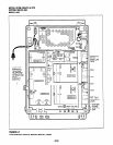
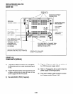
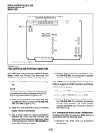
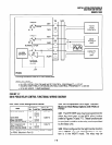
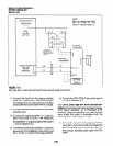
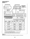
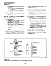
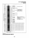
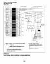
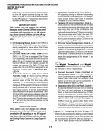
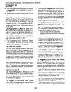
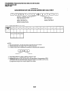
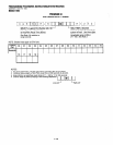
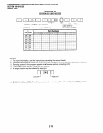
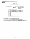
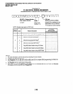
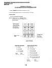
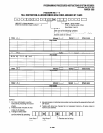
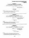
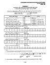
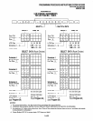
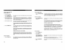
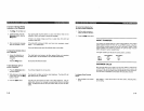
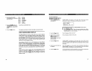
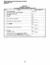
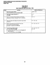
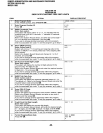
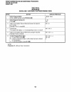
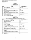
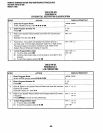
PIOUS
MAINTENANCE
CARD i
PORT
l
8-BIT
. NO-PARITY
l
l-STOP BIT
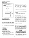
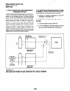
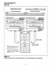
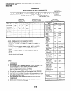
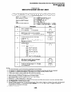
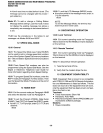
NOTE: 600 ohm Page
,r\
is not funcfior,,,
I I
on DK16
I OHM
GE
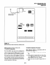
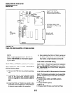
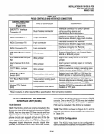
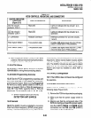
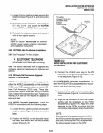
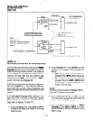
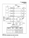
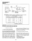
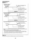
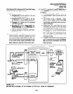
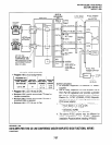
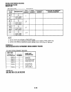
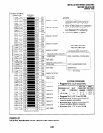
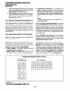
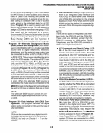
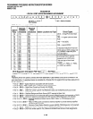
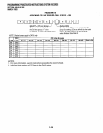
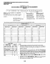
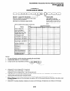
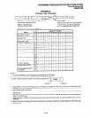
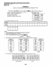
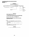
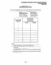
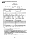
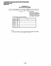
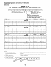
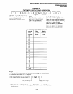
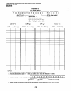
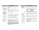
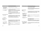
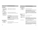
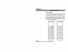
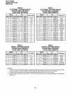
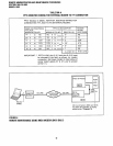
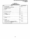
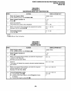
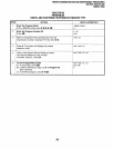
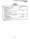
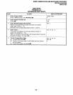
NOTE 3: PIOUS option settings:
SW1 - Sets the SMDR baud rate
to be 300 or 1200 BPS.
S W2 - Sets the PlOlJ programming speed to be
300 or 1200 BPS (for IMDU or TTY jack).
LED CO4 “On” = 300 BPS/SW2 set “In”.
LED CO4 “Ow’= 1200 BPS/SW2 set “Out”.
SW3 - Sets the PIOUS to operate with the
IMDlJ or an external device
connected to the l7Y modular jack.
~~_
- For IMDU operation (7, even, 1) MODEM
-l-l-Y
- For ASCII terminal (8, none, 1)
or external modem (8, none, 1).
W4 - Sets the IMDU and TTY jack
for bell or CC177 specification.
BELL - “W4 not installed”.
1 I
I,1 cc
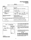
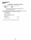
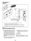
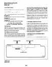
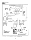
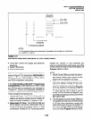
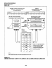
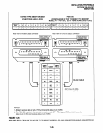
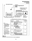
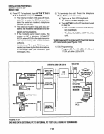
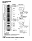
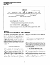
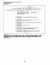
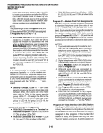
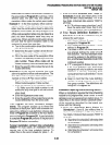
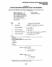
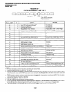
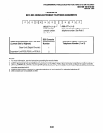
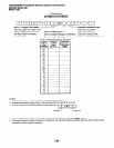
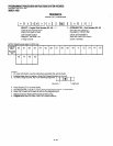
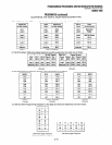
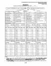
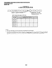
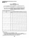
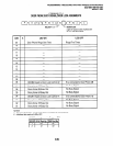
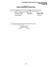
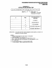
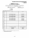
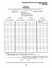
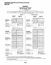
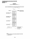
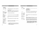
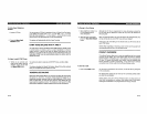
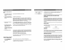
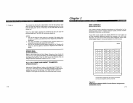
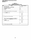
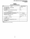
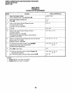
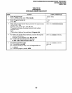
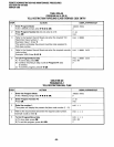
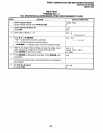
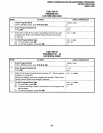
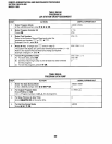
PIOU MODULAR PIN-OUT
PIN NO.1 l-’ ’
- 6 TYSG 1 SMSG
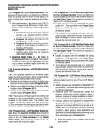
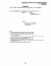
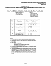
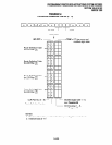
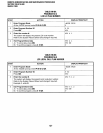
PPTC PIN-OUT
IOR LOCK,’
IP, MUTE
““1 F ALARM (
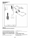
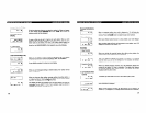
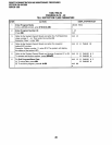
NOTE 4: PDIlJ-DS jumpers should be set to
the B-C position when connected
to the PIOUS TTY or SMDR port.
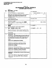
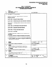
FIGURE 8-24
DK16 PIOUS/TTY AND SMDR WIRING
8-28