


2)
3)
4
l
Program
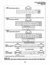
20: Port 04. LEDs 01, 02, 03,
04, 06, and 17 ON; all other LEDs OFF.
l
Program
21: Digital port 04 assigned
with PSTU port 08.
l
Program 39:
Port 00. Data Call (56),
Data Release (54), and Modem (55)
buttons should be provided.
l
Program 81:
Port 08. LED 01 ON (CO
line 01 rings QSTWKSTU port 08).
l
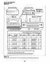
Internal modem: set to auto answer
(SO=l).
l
Default settings for PDIU-DI and PDIU-
DS, S-Registers.
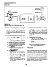
Make sure PC 1 and PC 2 are on-line with a
communications software package and that
the communication parameters of each PC
and communication software package are set
to the same values (data transmission rate,
parity, data bits, stop bits, flow control, etc.).
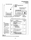
From PC 2’s keyboard, type
A
T D T 5 8 3
37
0
0
0
0
0
8
0 0 and press ENTER.
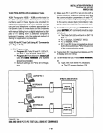
The external modem originates the call
to STRATA DK16 CO line 01.
CO line 01 rings incoming to the internal
modem (QSTU or KSTU port 08).
The internal modem rings and auto an-
swers; the modems handshake and es-
tablish communications.
If the modems send result codes, the
PC’sscreensdisplay, CONNECTXXXX,
where XXXX is the data transmission
speed set by the communications soft-
ware.
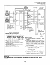
At this time, PC 2 is connected to PDIU-
DS (14), as shown by the thick lines
above (PDIU-DS 14 is in the command
mode). PC 2 can now issue AT com-
mands to PDIU-DS 14.
If DigitaVPDIU-DS port 04 is the only
PDIU port connected to a modem
(Pro-
gram
20, LED 03 ON), then the Modem
LEDs on all DKTs will light.
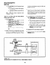
From PC 2’s keyboard, type AT D D 10 and
press ENTER (AT commands must be capi-
tal letters); this prompts PDIU-DS (14) to dial
and connect to PDIU-DI (10).
INSTALLATION-PERIPHERALS
SECTION 100-816-207
MARCH 1993
l
The CONNECT LED on the PDIU-DS
(14) will be lit; the Data Call and Modem
LEDs on DKT 10 will also be lit.
l
The screens on PC 1 and PC 2 display,
CONNECT XXXX, where XXXX is the
data transmission speed set by the com-
munication software.
l
At this time, PC 1 and PC 2 are con-
nected, as shown by the thick lines, to
exchange data (file transfers, typed mes-
sages, etc.).
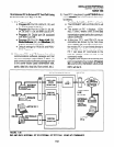
5) To terminate the call: Press the telephone
Data Release button, and
a) Type + + + from PC2 keyboard.
l
The PC screen displays, OK.
b) Type A T H from the PC keyboard used
in step 5a.
l
PC l’s and PC 2’s screens both dis-
play, NO CARRIER.
l
The DATA and MODEM LEDs on
DKT 10 will turn off.
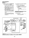
10.86 PC Auto Dial Voice Call Test (see Figure
7-38)
There are many off-the-shelf, IBM/MS-DOS com-
patible, desktop organizer software packages that
provide an auto dialer function. One of these is the
terminal resident SideKick. It is used in this section
for test explanation purposes only. If you choose
another auto dialer software package, the detailed
response may be different than that shown here.
1) DIU Programming:
Program
20: Port 01. LEDs 01,02, and 17
ON; all other LEDs OFF.
Program
39: Port 01. Data Call (56) and
Data Release (54) buttons are optional; if
the PDIU-DI is only used for the PC auto dial
application, the Data Call and Data
Release buttons are unnecessary.
2) Make sure that the auto dial application soft-
ware is installed on the PC root directory and
that the communication parameters of the
PC
and application software are set to the same
values (in this test example, Sidekick
“SKINSTAL” program).
7-55