


INSTALLATION-DK 16 KSU 81 PCB
SECTION 100-816-205
MARCH 1993
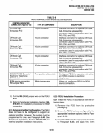
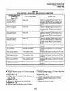
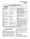
TABLE 5-E
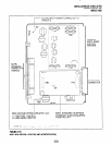
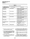
PCOUCONTROLS,INDICATORS,ANDlNTERFACECONNECTORS
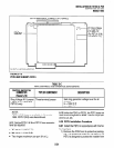
CONTROL/INDICATOR/
CONNECTOR
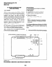
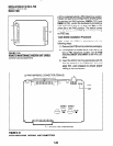
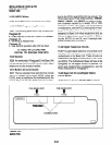
(Figure 5-17)
CO Line Circuit 1
Indicator CD1 12
CO Line Circuit 2
Indicator CD21 2
CO Line Circuit 3
Indicator CD31 2
CO Line Circuit 4
Indicator CD41 2
TYPE OF COMPONENT
Red LED
Red LED
Red LED
Red LED
DESCRIPTION
Lights to indicate CO line circuit 1 is in
operation (NOTE: CO line indicator will
not light unless PCOU is connected to
a CO).
Lights to indicate CO line circuit 2 is in
operation (NOTE: CO line indicator will
not light unless PCOU is connected to
a CO).
Lights to indicate CO line circuit 3 is in
operation (NOTE: CO line indicator will
not light unless PCOU is connected to
a CO).
Lights to indicate CO line circuit 4 is in
operation (NOTE: CO line indicator will
not light unless PCOU is connected to
a CO).
Jl Connector
J2 Connector
Modular connector
Modular connector
Two-position slide
Two-position slide
Two-position slide
Two-position slide
Interface connector for CO line circuits
1 and 2.
Inter-face connector for CO line circuits
3 and 4.
PAD Switch SW101 Enables 3dB signal level drop for CO line
circuit 1.
PAD Switch SW201 Enables 3dB signal level drop for CO line
circuit 2.
PAD Switch SW301
Enables 3dB signal level drop for CO line
circuit 3.
PAD Switch SW401 Enables 3dB signal level drop for CO line
circuit 4.
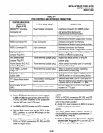
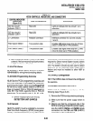
Program 41
l
Assigns stations access to CO lines (outgoing
l
Assigns special ringing of CO lines: Night Ring
only).
Program 42-O, l-8
l
Assigns behind PBXKENTREX operation to
each CO line.
Programs 45 - 48
l
Defines Toll Restrictions for any CO line.
Programs 50 - 56
Over Page, DISA, IMDU.
Programs 81 - 89
l
Assigns CO lines to ring selected stations.
l
Assigns Delayed Ringing to any CO line.
Program 93
l
Assigns names to CO lines.
l
Defines Least Cost Routing using CO lines.
Program 78
5-27