


-.
INSTALLATION-OK16 KSU & PCB
SECTION 100-816-205
MARCH 1993
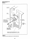
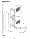
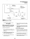
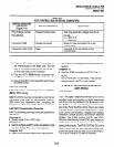
TWO-PRONG
MALE CONNECTOR
(PRE-ASSEMBLED)
BA-ITERY CABLE
WITH RING TERMINALS
AND PPSU CONNECTOR
(LENGTH 9 FEET)
ACTUAL
I-ItilJKt S-Y
RESERVE POWER/BATTERY WIRING
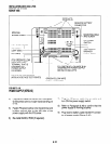
3 POWER SUPPLY REMOVAL AND
REPLACEMENT
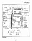
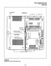
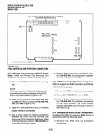
3.00 The power supply (KSPU 16) comes factory-
installed in the Base Key Service Unit (Figure510);
if necessary, it can be removed and replaced.
5) Remove FG screw from left side of power
supply to free FG wire/terminal and building
ground wire.
6) Remove the six screws that attach the power
supply to the Base Key Service Unit. Remove
power supply.
3.10 Power Supply Removal
3.20 Power Supply Replacement
1) Make sure that the power supply switch is
OFF and that the AC power cable is not
plugged into an outlet. Confirm that green AC
LED is not lit.
2) Unplug reserve battery cable from BATT con-
nector of power supply (Figure 5-10).
3) Remove K4RCU PCB and Expansion Unit
4) Unplug the DC cable from the DC OUT con-
nector (see Figure 5-10).
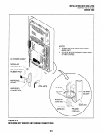
1) Route FGl wire (soldered on both sides of
Base Unit motherboard) so it will be under the
power supply inside of standoffs (see Figure
5-l 0).
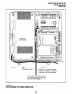
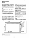
2) Set the power supply in its proper place in the
Base Key Service Unit (see Figure 5-9).
3) Secure the power supply to the Base Key
Service Unit with the six screws.
5-11