


INSTALLATION-SITE REQUIREMENTS
SECTION lOO-816-202
MARCH1993
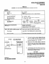
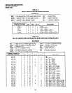
TABLE 2-A
SUMMARY OF ELECTRICAL/ENVIRONMENTAL CHARACTERISTICS
GENERAL
Primary power
Input AC
AC frequency
Power
Environmental specifications
Operating temperature
Operating humidity
Storage temperature
Power supply
DC voltage output
specification
Battery charger characteristics
(DK16
only)
QSTU, KSTU, PSTU or PESU (circuits 1 & 2)
Ring voltage
Ringing capability
85 - 135VAC
50/60 Hz
DK8-46 watts maximum, DK16-75 watts maximum
32 - 104°F (0 - 40°C)
20 - 80% relative humidity without condensation
- 4 - 158°F (-20 - 70°C)
DK16 DK8
-24VDC: (-26.3 - -27.8VDC)
+24VDC: (+26.3 - +27.8VDC)
+5VDC: ( +4.5 - +5.5VDC) +5VDC: ( +4.5 - +5.5VDCj
-5VDC: ( -4.5 - -5.5VDC) Note: +5V converter
on KSU PCB
Charger: current limiting
Nominal float voltage: 2.275 volts/cell
Charge current: 0.7 amps maximum
Battery discharge cut-off voltage: 20.5 + 0.5VDC
Square wave output with high/low option jumper:
Low position, 130 + 20VDC peak-to-peak (no-load)
High position, 190 f 25VDC peak-to-peak (no-load)
Two ringers maximum per circuit, high or low position
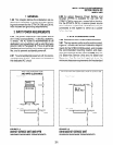
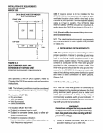
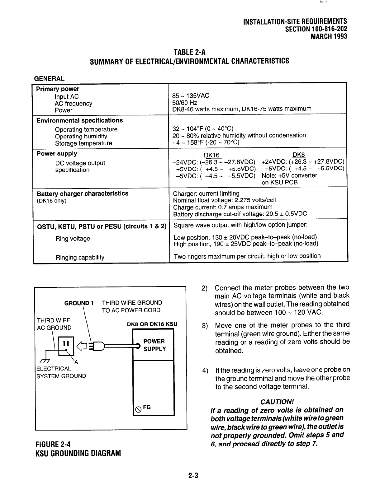
GROUND
1
THIRD WIRE GROUND
\
TO
AC POWER CORD
ELECTRICAL
SYSTEM GROUND
8 FG
FIGURE 2-4
KSU GROUNDING DIAGRAM
2) Connect the meter probes between the two
main AC voltage terminals (white and black
wires) on the wall outlet. The reading obtained
should be between 100 - 120 VAC.
3) Move one of the meter probes to the third
terminal (green wire ground). Either the same
reading or a reading of zero volts should be
obtained.
4) If the reading is zero volts, leave one probe on
the ground terminal and move the other probe
to the second voltage terminal.
CAUTION!
If a reading of zero volts is obtained on
both voltage terminals (white wire to green
wire, black wire to green wire), the outlet is
not properly grounded. Omit steps 5 and
6, and proceed direct/y to step 7.
2-3