


Chapter 14 Policy and Static Routes
ISG50 User’s Guide
295
Incoming Select where the packets are coming from; any, an interface, a tunnel, or the
ISG50 itself. For an interface or a tunnel, you also need to select the individual
interface or VPN tunnel connection.
Source Address Select a source IP address object from which the packets are sent.
Destination
Address
Select a destination IP address object to which the traffic is being sent. If the
next hop is a dynamic VPN tunnel and you enable Auto Destination Address,
the ISG50 uses the local network of the peer router that initiated an incoming
dynamic IPSec tunnel as the destination address of the policy instead of your
configuration here.
DSCP Code Select a DSCP code point value of incoming packets to which this policy route
applies or select User Defined to specify another DSCP code point. The lower
the number the higher the priority with the exception of 0 which is usually given
only best-effort treatment.
any means all DSCP value or no DSCP marker.
default means traffic with a DSCP value of 0. This is usually best effort traffic
The “af” choices stand for Assured Forwarding. The number following the “af”
identifies one of four classes and one of three drop preferences. See Assured
Forwarding (AF) PHB for DiffServ on page 299 for more details.
User-Defined
DSCP Code
Use this field to specify a custom DSCP code point.
Schedule Select a schedule to control when the policy route is active. none means the
route is active at all times if enabled.
Service Select a service or service group to identify the type of traffic to which this policy
route applies.
Next-Hop
Type Select Auto to have the ISG50 use the routing table to find a next-hop and
forward the matched packets automatically.
Select Gateway to route the matched packets to the next-hop router or switch
you specified in the Gateway field. You have to set up the next-hop router or
switch as a HOST address object first.
Select VPN Tunnel to route the matched packets via the specified VPN tunnel.
Select Trunk to route the matched packets through the interfaces in the trunk
group based on the load balancing algorithm.
Select Interface to route the matched packets through the specified outgoing
interface to a gateway (which is connected to the interface).
Gateway This field displays when you select Gateway in the Type field. Select a HOST
address object. The gateway is an immediate neighbor of your ISG50 that will
forward the packet to the destination. The gateway must be a router or switch on
the same segment as your ISG50's interface(s).
VPN Tunnel This field displays when you select VPN Tunnel in the Type field. Select a VPN
tunnel through which the packets are sent to the remote network that is
connected to the ISG50 directly.
Auto
Destination
Address
This field displays when you select VPN Tunnel in the Type field. Select this to
have the ISG50 use the local network of the peer router that initiated an
incoming dynamic IPSec tunnel as the destination address of the policy.
Leave this cleared if you want to manually specify the destination address.
Trunk This field displays when you select Trunk in the Type field. Select a trunk group
to have the ISG50 send the packets via the interfaces in the group.
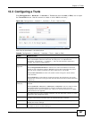
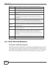
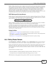
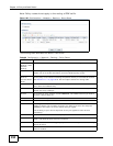
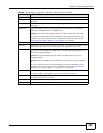
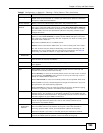
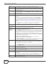
Table 87 Configuration > Network > Routing > Policy Route > Edit (continued)
LABEL DESCRIPTION