


A7 PCB, LO3 The A7, Third Local Oscillator (LO3) Assembly, provides a fixed
2.42 MHz Local Oscillator signal that is used on the A3, A4, and A6 PCBs
to down-convert the 2.5 MHz IF signals to 80 kHz. It also provides an 80
kHz standard signal for the IF Section Calibration process that occurs au
-
tomatically approximately every six minutes. This automatic IF Section
Calibration is one of the 373XXA features that ensures rated measure
-
ment accuracy. Automatic IF Calibration can be turned off and/or invoked
at any time during measurement sweeps.
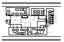
A5 A/D Converter PCB The A5 A/D Converter PCB contains a six-channel, two stage,
switched-filter sample-and-hold circuit and a 20 bit A/D converter. Each
of the six DC signals from the A3, A4, and A6 PCBs are input to a sepa
-
rate channel of the PCB. The first stage of each channel is a low-pass fil
-
ter with four selectable cutoff frequencies of 10 kHz, 1 kHz, 100 Hz, and
10 Hz. The second stage of each channel is a sample-and-hold amplifier
that stores the signals during the A/D conversion process. Each channel
is sequentially selected for input to the 20 bit A/D converter.
The A5 A/D Converter PCB also derives the 109.89 kHz Power Supply
Synchronization Signal and the 80 kHz IF Synchronization Signal
from the 10 MHz Reference Timebase. Additional functions of the A5,
A/D Converter Assembly include:
q
Measurement of power supply voltages and other internal nodes
of the 372XXB for diagnostic purposes.
q
Measurement of an externally applied analog input signal. This
function is used for service purposes only.
q
External Trigger Input signal processing (from rear panel)
q
External Analog Output signal generation (to rear panel)
The A/D converter circuitry located on the A/5 PCB is used as a DVM
to measure various internal system analog monitor points on the
A1 – A8 and A21A1/ A21A2 PCBs. It is also used to monitor power
supply voltages and other critical points throughout the 373XXA,
which can be readout via the Diagnostics Menus. DVM readings are
also recorded in the service log for certain system failures.
ANALOG SUBSYSTEM ASSEMBLIES SYSTEM DESCRIPTION
7-12 373XXA MM