8-7 A24 VME BUS
TERMINATOR PCB
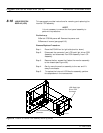
This paragraph provides instructions for removing and replacing the
A24 VME Bus Terminator PCB assembly.
Preliminary:
q
Switch 373XXA power off. Remove the power cord.
q
Remove bottom cover (paragraph 8-3).
Remove/Replace Procedure
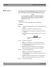
Step 1. Place the 373XXA on its top (bottom-side up).
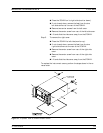
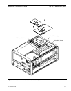
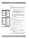
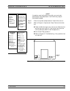
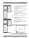
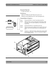
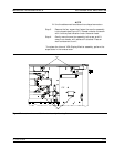
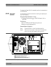
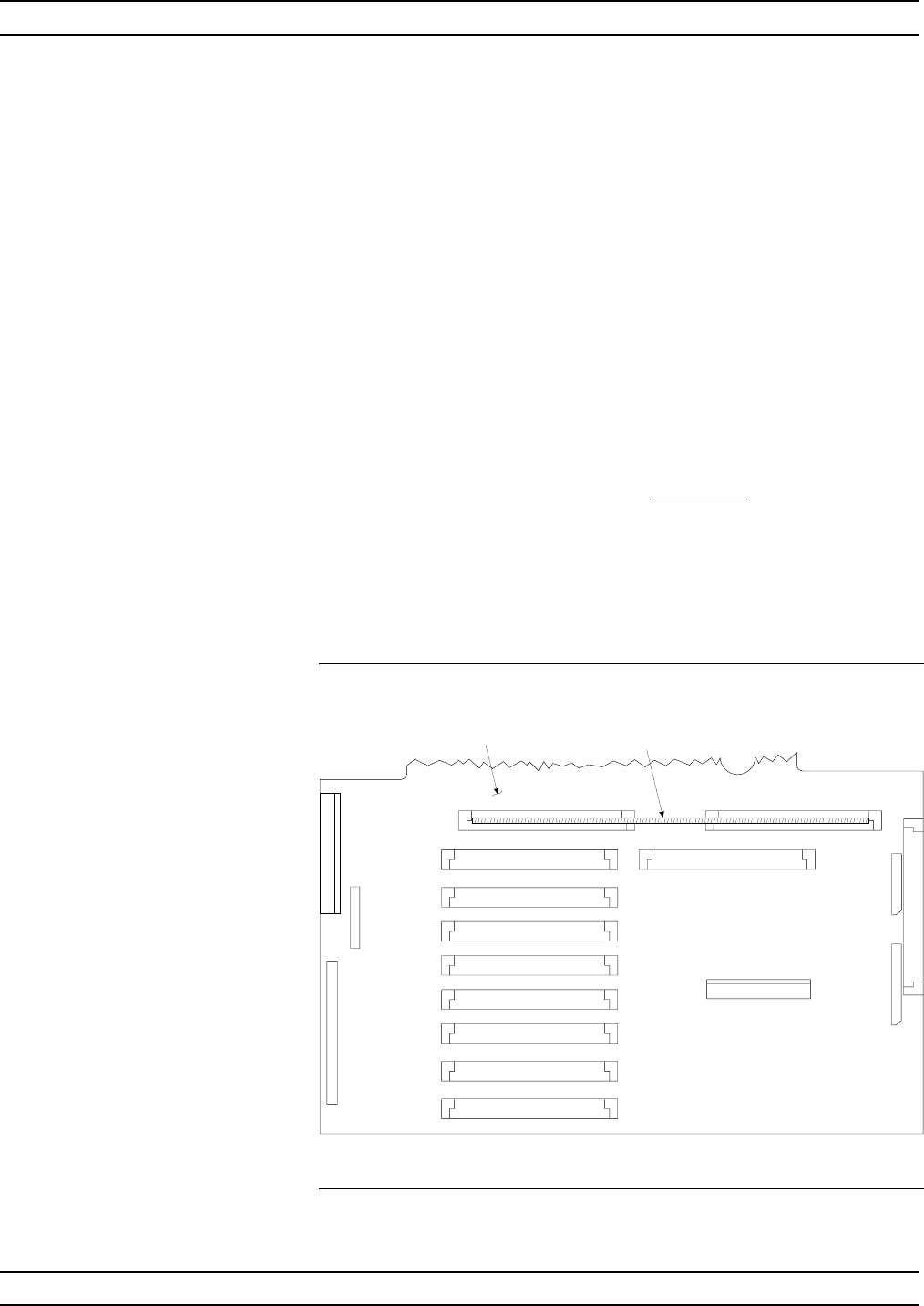
Step 2. Locate the A24 PCB assembly (Figure 8-5). Unplug A24
PCB assembly from the A17 Motherboard PCB by gently
pulling straight up on each side.
CAUTION
Be careful not bend or disturb the hard
co-ax lines located near right edge of A24
PCB.
8-8 FRONT PANEL
ASSEMBLY
This paragraph provides instructions for removing and replacing the
373XXA Front Panel assembly.
A24 VME BUS TERMINATOR PCB REMOVE AND REPLACE
8-12 373XXA MM
A24 VME Bus Terminal
PCB Assembly
A17 Motherboard
PCB Assembly
Figure 8-5. Location of the A24 VME Bus Terminator PCB Assembly


