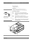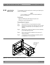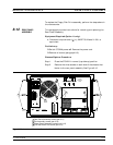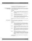
Step 3. Remove the two screws located near top and middle of rear
panel (near fan-mounting screws). See Figure 8-10.
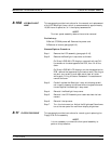
Step 4. Locate cable from the rear-panel 10 MHz Ref In BNC con
-
nector to connector J2 of A7 PCB. Disconnect at A7, J2 end.
(Pull up gently to disconnect.)
Step 5. Locate cable from the rear-panel 10 MHz Ref Out BNC
connector to connector J3 of A7 PCB. Disconnect at A7, J3
end.
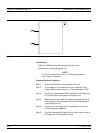
Step 6. Locate cable from the rear-panel Ext Anlg In BNC connec
-
tor to connector J1 of A5 PCB. Disconnect at A5, J1 end.
Step 7. Place the 373XXA on its right side (monitor down).
Step 8. Locate the cables from the rear-panel Ext Trigger and Ext
Anlg Out BNC connectors to connector P13 of the A18 Rear
Panel PCB. Disconnect at A18, P13 end. (A18, P3 is the
fourth connector away from the rear panel bottom lip.)
Step 9. Disconnect the large ribbon cable from connector P1 of the
A18 PCB at motherboard connector J12.
Step 10. Disconnect the two cables from the Power Supply Module
at motherboard connectors J4 and J13.
Step 11. Disconnect power cord from the Power Supply Module to
the internal VGA Display Monitor at the display monitor.
Step 12. If373XXA is equipped with Option 11, Reference Loop Ex
-
tension Cables:
n
Using a
5
16
in. wrench, disconnect the external cable
Loops from the rear panel connectors.
n
Using a
5
16
in. wrench, disconnect the semi-rigid coaxial
lines W141 and W145 at the inside of the rear panel. See
Figure 8-11 on page 8-23.
Step 13. If373XXA is equipped with Option 10, High Stability Time
Base:
n
Locate output cable from the high stability oscillator as
-
sembly (mounted above Power supply Module) to connec
-
tor J1 of A7 PCB. Disconnect at A7, J1 end.
n
Locate power cable from the high stability oscillator as
-
sembly to A17 Motherboard connector, J18. Disconnect
at A17, J18 end.
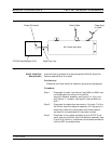
Step 14. Place the373XXA in normal (top-side up) position. Gently
pull rear panel assembly away from chassis and lay flat on
REAR PANEL ASSEMBLY REMOVE AND REPLACE
8-20 373XXA MM


