


APPENDIX D PERFORMANCE SPECIFICATIONS
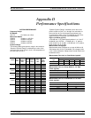
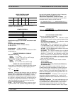
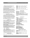
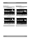
Throughput Times (ms) without Correction (typical)
Data Format 3 Points* 101 Points 401 Points 1601 Points
32 Bit 230 650 1400 3600
64 Bit 230 680 1450 4000
ASCII 235 800 1700 5000
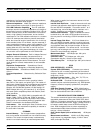
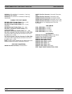
Throughput Times (ms) with Correction (typical)
Data Format 3 Points* 101 Points 401 Points 1601 Points
32 Bit 340 1200 2600 7800
64 Bit 350 1200 2700 8300
ASCII 350 1280 3000 9300
* Frequencies taken at 2, 4, and 6 GHz
GENERAL
37300A Front Panel Connectors and Controls:
Keyboard Input: An IBM-AT compatible keyboard can
be connected to the front panel for navigating through
front panel menus and disk directories, annotation of data
files and display labels, printing displays and pausing in
-
strument sweeps.
Test Ports: Universal/K, male, connectors are standard
on all models except for 37397A, which has V Connector
test ports as standard. For other configurations check Op-
tion 7. For additional configurations check Test Port Con-
verters.
Bias Inputs: Port 1 and 2: 0.5 amps maximum through
BNC connectors.
Port 1 Amplifier Loop: Access to insert an external
amplifier, ahead of the port 1 coupler or bridge, to in-
crease port 1 power output, up to +30 dBm (1 watt) maxi
-
mum.
37300A Rear Panel Connectors and Controls:
PRINTER OUT: Centronics interface for an external
printer.
VGA OUT:
Provides VGA output of 373XXA video dis
-
play.
10 MHz REF IN: Connects to external reference fre
-
quency standard, 10 MHz, +5 to –5 dBm, 50 ohms, BNC
female.
10 MHz REF OUT: Connects to internal reference fre
-
quency standard, 10 MHz, 0 dBm, 50 ohms, BNC female.
EXT ANALOG OUT: –10V to +10V with 5 mV resolu
-
tion, varying in proportion to user-selected data (e.g., fre
-
quency, amplitude). BNC female.
EXT ANALOG IN:
±50 volt input for displaying external
signals on the CRT in Diagnostics mode. BNC female.
LINE SELECTION: Power supply automatically
senses 100V, 120V, 220V or 240V lines.
EXTERNAL TRIGGER: External triggering for 373XXA
measurement, ±1V trigger. 10 kohm input impedance.
BNC female.
REFERENCE EXTENSION: Provides access to a1
and b1 samplers; K or V Connector, female.
EXTERNAL SCSI: Provides SCSI-2 connector for con
-
nection of an external SCSI hard disk drive (Opt. 4).
EXTERNAL I/O: 25-pin DSUB connector.
EXTERNAL SCSI: Provides SCSI-2 connector for con
-
nection of an external SCSI hard disk drive (Opt. 4).
SERIAL: Provides control for AutoCal module.
LIMITS PASS/FAIL: Selectable TTL levels
(Pass=0V, Fail=+5V or Pass=+5V, Fail=0V. Addi
-
tionally, 0 volts (all displayed channels pass) or +5V
(any one of 4 displayed channels fail) output pass/fail
status (1 line).
EXTERNAL TRIGGER: External triggering for
373XXA measurement, ±1V trigger. 10 kohm input im
-
pedance. BNC female.
EXT ANALOG OUT: –10V to +10V with 5 mV reso
-
lution, varying in proportion to user-selected data (e.g.,
frequency, amplitude). BNC female.
Power Requirements: 85-240V, 48-63 Hz, 540 VA maxi
-
mum
Dimensions: 267H x 432W x 585D mm (10.5H x 17W x
23D in.)
Weight: 34 kg (75 lb) - Maximum amount specified for
2-man lift requirement.
ENVIRONMENTAL
Storage Temperature Range: –40°Cto+75°C
Operating Temperature Range: –0°Cto+50°C
Relative Humidity: 5% to 95% at +40°C
EMI: Meets the emissions and immunity requirements of
EN55011/1991 Class A/CISPR-11 Class A
EN 50082-1/1993
IEC 801-2/1984 (4 kV CD, 8kV AD)
IEC 1000-4-3/1995 (3 V/m, 80-1000 MHz)
IEC 801-4/1988 (500V SL, 1000V PL)
IEC 1000-4-5/1995 (2 kV L-E, 1kV L-L)
GAIN COMPRESSION MEASUREMENT CAPABILITY
The 373XXA simplifies amplifier Gain Compression and
AM/PM measurements. Once an appropriate power and
frequency schedule is selected, a power meter calibration,
at a set level, will calibrate the linear VNA receiver chan
-
nels, to accurately measure power in dBm. The 37300A
supports the HP437B, and Giga-tronics 8540B series
power meters. To measure power, b2/1, a user defined pa
-
rameter, is automatically selected.
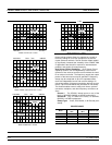
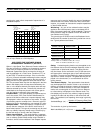
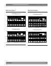
Swept Power Gain Compression: The 373XXA will dis
-
play traditional Power out vs. Power in or Phase vs. Power
in, at one of up to 10 selectable frequencies. A separate
screen will easily show Power out and Power in at 1 dB, or
selected level Gain Compression, for all entered frequen
-
cies. (Check figure below).
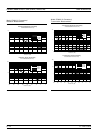
Swept Frequency Gain Compression: Once Gain is
measured at the starting power, the user increments Power
in, observing Normalized Gain vs. Frequency. This aids in
D-9 373XXA OM