


8-4 A1–A9 AND A13–A16
PCBS
This paragraph provides instructions for removing and replacing the
A1– A9 and A13 – A16 PCB’s, which are located underneath the cov
-
ers of the large and small card-cages, respectively.
Preliminary:
q
Switch the 373XXA power off. Remove the power cord.
Remove the top cover (paragraph 8-3).
A1 – A9 PCBs
Procedure:
Step 1. Place the 373XXA in normal (top-side up) position.
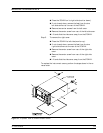
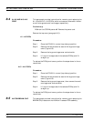
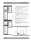
Step 2. Remove the two screws that secure the large card-cage
cover (Figure 8-2).
Step 3. Remove the large card-cage cover and set aside.
Step 4. Lift up on the edge tabs of the selected PCB(s) and lift
straight up.
To replace the PCB(s) and covers, perform the steps above in the re-
verse order.
A13 – A16 PCB’s
Procedure:
Step 1. Place the 373XXA in normal (top-side up) position.
Step 2. Remove the two screws that secure the large card-cage
cover (Figure 8-2).
Step 3. Remove the large card-cage cover, then remove the small
card-cage cover and set aside.
Step 4. Lift up on the edge tabs of the selected PCB(s) and lift
straight up.
To replace the PCB(s) and covers, perform the steps above in the re
-
verse order.
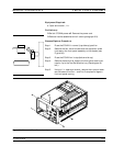
8-5 A9 PCB BBRAM CHIP This paragraph provides instructions for removing and replacing the
BBRAM Chip located on the A9 Main Processor PCB assembly.
A1–A9 AND A13–A16 PCBS REMOVE AND REPLACE
8-6 373XXA MM