


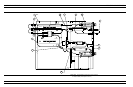
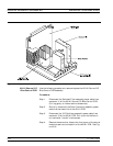

A21A2 Source Control
PCB
Use the following procedure to remove/replace the A21A2 Source Con-
trol PCB assembly.
Procedure:
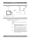
Step 1. Unfasten the two PCB retainers at the top corners of the
A21A2 Source Control PCB (see Figure 8-16). To unfasten,
turn screwdriver slot
1
4
turn counter-clockwise.
Step 2. Pull the top of the A21A2 PCB away from the source mod
-
ule chassis back plate to clear PCB retainers. Gently pull
up to disconnect the A21A2 PCB from the socket on the
A21A1 Source YIG Bias Control PC. Remove from Source
Module.
To replace the A21A2 Source Control PCB assembly, perform the steps
above in the reverse order.
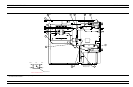
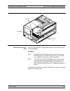
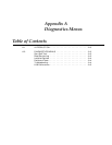
REMOVE AND REPLACE SIGNAL SOURCE MODULES
373XXA MM 8-31
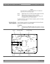
Side Rail Mounting
Screws
Captive Screws
A21A2 Source
Control PCB
Figure 8-15. Signal Source Module Removal Details