


A21A1 Source YIG
Bias Control PCB
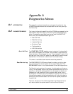
Use the following procedure to remove/replace the A21A1 Source YIG
Bias Control PCB assembly.
Procedure:
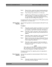
Step 1. Disconnect the Switched Filter assembly power cable from
connector J1 of the A21A1 Source YIG Bias Control PCB.
(Pull up gently on ribbon cable to disconnect.)
Step 2. Similarly, disconnect the Down Converter assembly power
cable from connector J4 of the A21A1 PCB.
Step 3. Disconnect the YIG Oscillator assembly power cable from
connector J3 of the A21A1 PCB. Pull up on the flexible cir
-
cuit connector “handle” to disconnect.
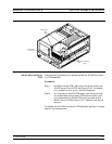
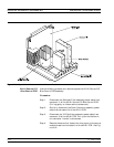
Step 4. Remove the screw that fastens the front apron of the source
module chassis to the heatsink of the A21A1 PCB. See Fig
-
ure 8-16.
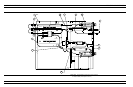
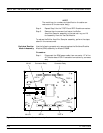
SIGNAL SOURCE MODULES REMOVE AND REPLACE
8-32 373XXA MM
Figure 8-16. Signal Source Module Assemblies Removal Details