


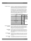


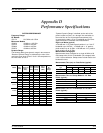
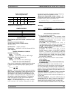
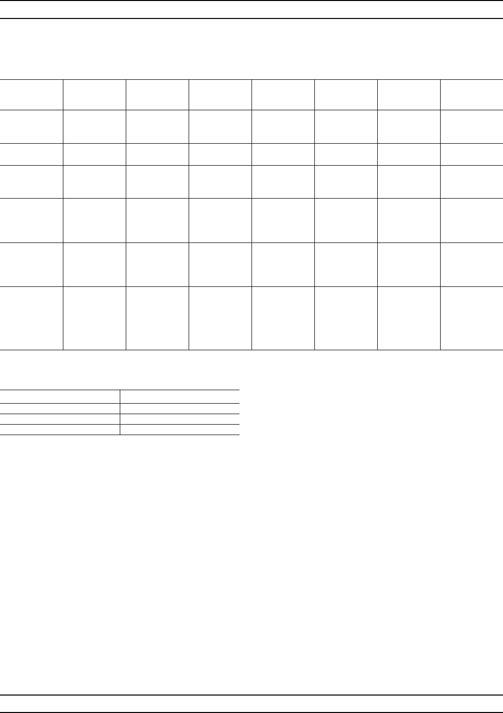
Measurement Time vs. Span for 101 Data Points (typi-
cal):
Frequency Span Time (ms)
40 MHz to 40 GHz 500
20 GHz to 40 GHz 400
10 GHz to 11 GHz 250
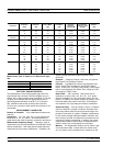
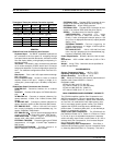
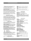
TEST PORT CHARACTERISTICS
The specifications in the following table apply when the
proper Model 34U Universal Test Port Adapters are con
-
nected, with or without phase equal insertables, to the test
set ports and calibrated with the appropriate Anritsu or
other designated calibration kit at 23°C ±3°C using the
OSL calibration method with a sliding load to achieve
12-Term error correction (A 90 minute warm-up time is rec
-
ommended.)
MEASUREMENT CAPABILITIES
Number of Channels: Four independent measurement
channels.
Parameters: S11, S21, S22, S12, or user-defined com
-
binations of a1, a2, b1, and b2. All measurements are
made without the need to manually reverse the test device.
Measurement Frequency Range: Frequency range of
measurement can be narrowed within the calibration range
without recalibration. CW mode permits single frequency
measurements, also without recalibration. In addition, the
system accepts N discrete frequency points where
2£N£1601.
Domains: Frequency Domain, CW Draw, and optional
High Speed Time (Distance) Domain.
Formats: Log Magnitude, Phase, Log Magnitude and
Phase, Smith Chart (impedance), Smith Chart (Admit
-
tance), Linear Polar, Log Polar, Group Delay, Linear Magni
-
tude, Linear Magnitude and Phase, Real, Imaginary, Real
and Imaginary, SWR, Power.
Data Points: 1601 maximum. Data points can be
switched to a value of 801, 401, 201, 101, or 51 points
without recalibration (if 1601 points were used in the cali
-
bration). In addition, the system accepts an arbitrary set of
N discrete data points where: 2£N£1601. CW mode per
-
mits selection of a single data point without recalibration.
Reference Delay: Can be entered in time or in distance
(when the dielectric constant is entered). Automatic refer
-
ence delay feature adds the correct electrical length com
-
pensation at the push of a button. Software compensation
for the electrical length difference between reference and
test is always accurate and stable since measurement fre
-
quencies are always synthesized. In addition, the system
compensates reference phase delay for dispersive trans
-
mission media, such as waveguide and microstrip.
Markers: Six independent markers can be used to read
out measurement data. In delta-reference marker mode,
any one marker can be selected as the reference for the
D-4 373XXA MM
PERFORMANCE SPECIFICATIONS APPENDIX D
Connector
Frequency
(GHz)
Directivity
(dB)
Source Match
(dB)
Load Match
(dB)
Reflection
Frequency
Tracking (dB)
Transmission
Frequency Track
-
ing (dB)
Isolation
(dB)
GPC-7 0.0225 >52 >44 >52
±0.003 ±0.004
>105
2.0 >52 >44 >52
±0.003 ±0.004
>115
18 >52 >42 >52
±0.004 ±0.012
>112
GPC-7 LRL
Calibration
2.0 >60 >60 >60
±0.001 ±0.001
>115
18 >60 >60 >60
±0.001 ±0.001
>112
N-Type 0.0225 >46 >36 >46
±0.004 ±0.004
>105
2.0 >44 >36 >44
±0.004 ±0.004
>115
18 >40 >32 >40
±0.005 ±0.012
>112
3.5 mm 0.0225 >44 >40 >44
±0.005 ±0.030
>105
2.0 >44 >40 >44
±0.005 ±0.030
>115
20 >44 >38 >44
±0.006 ±0.050
>110
26.5 >44 >34 >44
±0.006 ±0.070
>102
K 0.0225 >42 >40 >42
±0.005 ±0.030
>105
2.0 >42 >40 >42
±0.005 ±0.050
>115
20 >42 >34 >42
±0.006 ±0.070
>110
40 >38 >34 >38
±0.006 ±0.080
>100
V 0.04 >70 >36 >40 ±0.050 ±0.030 >105
2.0 >40 >36 >40 ±0.050 ±0.050 >115
20 >40 >36 >40 ±0.060 ±0.070 >110
40 >36 >32 >36 ±0.060 ±0.080 >100
50 >34 >30 >34 ±0.080 ±0.100 >90
65 >34 >28 >34 ±0.100 ±0.120 >80