


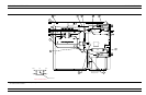
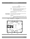
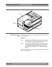

Step 2. Disconnect the semi-rigid coaxial line W81 from the input
connector of the SDM; see Figure 8-12.
Step 3. Remove the two screws that fasten the SDM to the Test Set
Module tray.
Step 4. Disconnect the semi-rigid coaxial line W80 from the output
connector of the SDM; see Figure 8-12. Carefully lift the as
-
sembly from the Test Set Module.
To replace the Switched Doubler Module assembly, perform the steps
above in the reverse order.
8-17 SIGNAL SOURCE
MODULES
The following paragraphs provide instructions for removing and re
-
placing the RF/microwave components that comprise the Signal
Source Module.
Equipment Required:
q
Connector torque wrench (
5
16
in), ANRITSU Model 01-201, or
equivalent.
CAUTION
Throughout these procedures, always use the
5
16
in. con-
nector torque wrench for connecting the Signal Source
Module semi-rigid coaxial lines and RF/microwave compo-
nents. Use of improper tools may damage the connectors,
resulting in degraded instrument performance.
Preliminary:
q
Switch373XXA power off. Remove the power cord.
q
Remove all covers (paragraph 8-3).
Removal of Signal
Source Module
Use the following procedure to remove the Signal Source Module from
the chassis. This step is necessary before any of the module compo
-
nents can be removed/replaced.
Procedure:
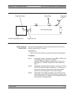
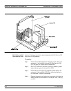
Step 1. Place the373XXA on its top (bottom-side up).
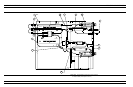
Step 2. At J2 on the motherboard PCB, disconnect the Floppy Con
-
trol (ribbon) cable that goes to the floppy drive. Dress the
ribbon cable away from the Signal Source Module output
connector; see Figure 8-11.
Step 3. Disconnect the semi-rigid coaxial line W87* from the out
-
put connector of the Signal Source Module.
Step 4. Place the373XXA in normal (top-side up) position.
REMOVE AND REPLACE SIGNAL SOURCE MODULES
373XXA MM 8-29