


NOTE
All the the cables mentioned above have keyed connectors.
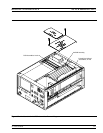
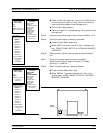
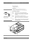
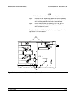
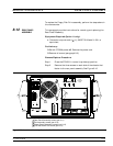
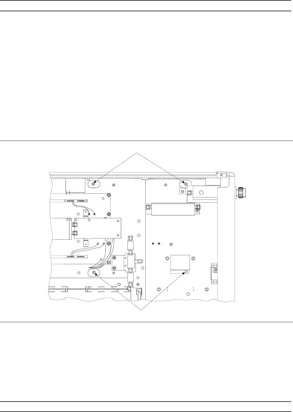
Step 3. Remove the four screws that fasten the monitor assembly
to the chassis (see Figure 8-7). Do not unfasten the screw
with the blue plastic washer under the screw head.
Step 4. Gently move the monitor assembly to the rear and lift
away from chassis, with cables still attached. Place on
work surface next to unit.
To replace the Internal VGA Display Monitor assembly, perform the
steps above in the reverse order.
REMOVE AND REPLACE VGA DISPLAY MONITOR
373XXA MM 8-15
J7
J2
TEST A
TEST A
TEST B
TEST B
J1
TP4
TP1
J2
TEST A
TEST A
TEST B
TEST B
J1
TP4
TP1
2 PL
2 PL
Figure 8-7. Location of Internal VGA Monitor Assembly Mounting Screws