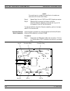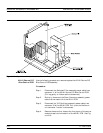
To replace the Transfer Switch assembly, perform the steps above in
the reverse order. W111 for Models 37211B and 37217B
Input Coupler(s)/ Low
Freq Bridge(s)
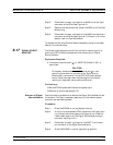
Use the following procedure to remove/replace the Input Coupler(s) of
all models 37225B through 37269B and the Low Frequency Bridges of
models 37211B and 37217B.
Procedure:
Step 1. Using a 1 in. open-end wrench, remove the front panel nut
and washer of the Port1or Port2 coupler/bridge that is to
be removed.
Step 2. Disconnect the two semi-rigid coaxial lines associated with
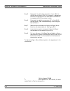
the coupler/bridge (see Figure 8-11).
Step 3. Remove the two screws that fasten the coupler/bridge
bracket to the test set tray. Move coupler/bridge to the rear
and up to remove it from the Test Set Module.
To replace the coupler/bridge, perform the steps above in the reverse
order.
Power Amplifier Use the following procedure to remove/replace the Power Amplifier as-
sembly, which is common to all373XXA models.
Procedure:
Step 1. Disconnect the Power Amplifier power cable at connector
J5 of the A17 Motherboard PCB. Free the cable by separat
-
ing it from the cable harness and by temporarily removing
the A24 VME Terminator PCB.
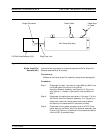
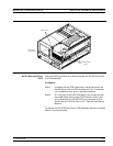
Step 2. Disconnect the PWR AMP IN cable on the side of the Power
Amplifier assembly; see Figure 8-13. (Pull out gently to dis
-
connect.)
Step 3. Remove the two screws that fasten the Power Amplifier as
-
sembly to the test set tray. Remove the two screws that fas
-
tens the assembly feet to the Buffer Amplifier/Sampler as
-
sembly.
Step 4. Disconnect the Power Amplifier from the Buffer
Amplifier/Sampler by carefully pulling up on the connector
end of the rigid-coaxial line from the Power Amplifier. (See
Figure 8-13.) Carefully lift the assembly from the Test Set
Module.
To replace the Power Amplifier assembly, perform the steps above in
the reverse order.
TEST SET MODULE ASSEMBLIES REMOVE AND REPLACE
8-26 373XXA MM


