D-10 373XXA MM
PERFORMANCE SPECIFICATIONS APPENDIX D
analyzing the most critical compression frequencies of a
broadband amplifier.
HIGH SPEED TIME (DISTANCE) DOMAIN
MEASUREMENT CAPABILITY (OPTION 2)
Option 2, High Speed Time (Distance) Domain software al-
lows the conversion of reflection or transmission measure-
ments from the frequency domain to the time domain.
Measured S-parameter data is converted to the time do-
main by application of a Fast Fourier Transform (FFT) us-
ing the Chirp Z-Transform technique. Prior to conversion
any one of several selectable windowing functions may be
applied. Once the data is converted to the time domain, a
gating function may be applied to select the data of inter
-
est. The processed data may then be displayed in the time
domain with display start and stop times selected by the
user or in the distance domain with display start and stop
distance selected by the user. The data may also be con
-
verted back to the frequency domain with a time gate to
view the frequency response of the gated data.
Lowpass Mode: This mode displays a response equiva
-
lent to the classic TDR (Time Domain Reflectometer) re
-
sponse of the device under test. Lowpass response may
be displayed in either the impulse or step mode. This type
of processing requires a sweep over a harmonic series of
frequencies and an extrapolated or user-entered DC value.
Bandpass Mode: This mode displays a response equiv
-
alent to the time response of the device under test to a
band limited impulse. This type of processing may be used
with any arbitrary frequency sweep range, limited only by
the test set range or device under test response.
Phasor Impulse Mode: This mode displays a response
similar to the Lowpass impulse response, using data taken
over an arbitrary (band limited) sweep range. Detailed in
-
formation, similar to that contained in the lowpass impulse
response may be used to identify the nature of impedance
discontinuities in the device under test. Now, with Phasor
Impulse, it is possible to characterize complex impedances
on band-limited devices.
Windowing: Any one of four window functions may be
applied to the initial frequency data, to counteract the ef
-
fects of processing data with a finite bandwidth. These win
-
dows provide a range of tradeoffs of main lobe width ver
-
sus sidelobe level (ringing).
The general type of function used is the Blackman-Harris
window with the number of terms being varied from one to
four. Typical performance follows:
Types of Window
(Number of Terms)
First Side Lobe
Relative to Peak
Impulse Width
1
Rectangular (1) –13 dB 1.2W
Nominal-Hamming (2) –43 dB 1.8W
Low Side Lobe,
Blackman-Harris (3)
–67 dB 2.1W
Minimum Side Lobe,
Blackman-Harris (4)
–92 dB 2.7W
1
W(Bin Width) = 1/2∆f sweep width
Example: When ∆f = 40 MHz to 40 GHz, W = 12.5 ps
When ∆f = 40 MHz to 65 GHz, W = 7.7 ps
Gating: A selective gating function may be applied to the
time domain data to remove unwanted responses, either in
a pass-band or reject-band (mask). This gating function
may be chosen as the convolution of any of the above win-
dow types with a rectangular gate of user defined position
and width. The gate may be specified by entering start and
stop times or center and span. The gated data may be dis
-
played in the time domain, or converted back to the fre
-
quency domain.
Time Domain Display: Data processed to time domain
may be displayed as a function of time or as a function of
distance, provided the dielectric constant of the transmis
-
sion media is entered correctly. In the case of dispersive
media such as waveguide or microstrip, the true distance
to a discontinuity is displayed in the distance mode. The
time display may be set to any arbitrary range by specify
-
ing either the start and stop times or the center time and
span. The unaliased (non-repeating) time range is given by
the formula:
UnaliasiedRange ns
Number of Frequency Data Points
Fre
()=
quency Sweep Range GHz()
The resolution is given by the formula:
Main LobeWidth null null in ns
kW
Freq Sweep Range GHz
(\)
()
=
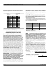
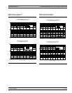
-12.00 dBm 8.00 dBm5.00000000 GHz CW
CH1:b
2
/1
POWER OUT
REF = 15.000 dBm
1.000 dB/DIV
CW MODE
CH3 : S21 FWD TRANS
PHASE
REF = 5.00°
2.00°/DIV
Phase
Power Out
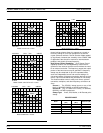
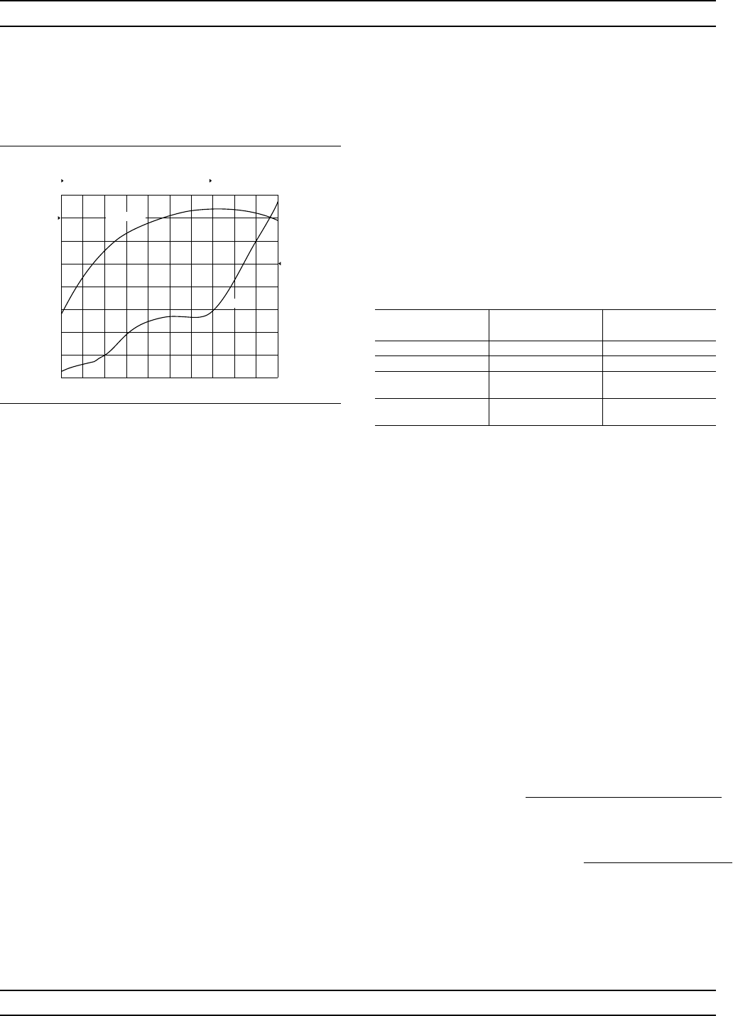
Shows Power Out and Phase performance as a func-
tion of Input Power at a CW frequency.


