


q
Front panel casting
NOTE
The front panel is an integrated assembly that is replace
-
able only as a single unit.
Rear Panel Assembly The Rear Panel Assembly includes the following rear panel connec
-
tors:
q
10 MHz Reference In and Out BNC connectors
q
External Trigger BNC connector
q
External Analog Input BNC connector
q
External Analog Output BNC connector
This assembly also includes:
q
Reference Channel Extension Loops (Option 11)
q
Main system fan
q
The A18 Rear Panel PCB and associated connectors, circuitry,
and cables (below).
A18 Rear Panel
Interface PCB
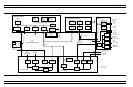
This PCB assembly contains the rear panel connectors listed below. It
also includes the associated circuitry and cabling interfaces that link
these connectors (and the rear panel fan assembly) to the A17 Mother-
board PCB and other assemblies within the 373XXA.
q
IEEE 488.2 GPIB connector (with associated interface circuits)
q
Dedicated GPIB connector (with associated interface circuits)
q
Printer Out connector (with associated interface circuits)
q
VGA Out connector
q
CRT degauss and brightness controls
q
I/O Connector (and associated interface circuits)– This 25 pin
miniature D-sub connector contains:
n
Limits Testing Status TTL outputs
n
Port 1 and Port 2 Bias Inputs.
n
Ext Dig In signal (same as External Trigger BNC)
n
Ext Ana Out signal (same as External Analog Output BNC)
The A18 PCB also contains:
q
Routing of –24 Vdc power to the rear panel system fan.
q
Routing of External Analog Out and External Trigger Input sig
-
nals to the Mother Board.
SYSTEM DESCRIPTION MAIN CHASSIS ASSEMBLIES
373XXA MM 7-17