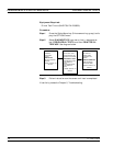
ANRITSU Verification Kit appropriate for the 373XXA model; refer
to paragraph 4-3.
GPIB cable (ANRITSU PN: 2100-2), or equivalent
Procedure:
Step 1. Using the GPIB cable, connect the external computer/con
-
troller to the IEEE 488.2 GPIB Interface port on the
373XXA rear panel.
Step 2. Insert the CD ROM into its drive and install the 2300-237
software.
Step 3. Follow the directions displayed on the computer screen to
perform all tests.
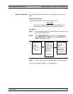
If the calibration fails, check the connectors of the calibra
-
tion kit devices and the impedance transfer standards for
damage, cleanliness, and proper connection and torquing.
These are the most common causes for verification failures.
If the problem persists, check system Directivity, Match,
and Dynamic Range, as described in the next paragraph.
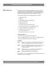
4-5 KEY SYSTEM
PARAMETERS
The following paragraphs describe procedures for automated measure-
ment of the key system performance parameters listed below. Measure-
ment of these parameters is not required for system verification; however,
it is highly recommended to ensure that the complete 373XXA measure-
ment environment is stable and capable of supporting accurate measure
-
ments.
q
Effective Source Match
q
Effective Directivity
q
System Dynamic Range
q
Frequency Accuracy
q
Power Level Accuracy
Measurement
Environment
Considerations
As with the verification procedures, the quality of the measurement of the
system performance parameters listed above is very dependent on the
measurement environment.
The complete 373XXA measurement environment consists of:
q
Condition and stability of the test ports, through-cable, and calibra
-
tion kit mating connectors.
q
Settings and stability of the surrounding environment, especially
temperature, humidity, and vibration. To maintain the highest sys
-
tem performance, avoid changing these conditions, especially tem
-
KEY SYSTEM PARAMETERS PERFORMANCE VERIFICATION
4-6 373XXA MM


