E
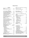
Electro-static discharge procedures ······1-9
EQUIPMENT REQUIRED ···········8-3
Error Code DE Lock Failure Troubleshooting 5-14
Error Codes ··················5-10
Error Messages
Disk Related ·················B-3
Disk Related Error Messages ········B-3
GPIB Related·················B-3
INTRODUCTION ··············B-3
Operational Error Messages·········B-3
Service Log ··················B-3
EXCHANGE ASSEMBLY PROGRAM ·····2-3
Exploded View of 372XXB Chassis Covers · · 8-5
External Keyboard Interface Test ·······3-7
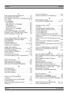
F
Factory Repairable Non-Exchange Parts ···2-6
Failed Assembly Exchange Program ······1-8
FAN ASSEMBLY ···············8-21
Field Service Kits ················1-7
FLOPPY DISK DRIVE ·········8-17 -8 -18
Floppy Disk Drive Assembly ·········7-16
Floppy Disk Problems··············5-9
FREQUENCY CALIBRATION ······6-5-6-7
Front Panel Assembly ·············7-16
FRONT PANEL ASSEMBLY······8-12 -8 -13
Front Panel Test·················3-7
Front Panel Test Failures ···········5-22
Functional Assembly Level Troubleshooting· · 1-5
G
GPIB Interface Test ···············3-9
GPIB Interface Test Failures ·········5-22
GPIB Related Error Messages ·········B-3
GPIB RELATED ERROR MESSAGES ····B-3
H
H/W Calibrations ················A-5
Hard Disk Problem 1 ··············5-8
Hard Disk Problem 2 ··············5-9
Hard Disk Problems ··············5-8
I
IDENTIFICATION NUMBER ·········1-3
IF Section····················7-11
Input Coupler(s)/ Low Freq Bridge(s)·····8-26
Installed Options ················A-4
Internal Hardware Adjustments and
Calibration ···················1-5
Internal VGA Monitor ·············7-19
Isolation Procedures, Troubleshooting ····5-19
K
Keep Connectors Clean·············C-4
KEY SYSTEM PARAMETERS······4-6-4-7
L
LCD BACKLIGHT LAMP ···········8-17
LCDTest·····················3-6
Line Source and Interface Checks ·······5-4
LIQUID CRYSTAL DISPLAY (LCD) ·····8-16
LO 2 CALIBRATION ··············6-4
LO1 CALIBRATION ··············6-3
Location of BBRAM Chip on the A9 PCB ···8-9
Location of Floppy Disk Drive Assembly Mounting
Plate Screws ··················8-18
Location of Internal LCD Assembly Mounting
Screws ·····················8-16
Location of Internal VGA Monitor Assembly
Mounting Screws················8-15
Location of Mounting Screws for Rear Panel As-
semblies ····················8-19
Location of SRAM Battery on the A9 PCB · · 8-11
Location of the A24 VME Bus Terminator
PCB Assembly ·················8-12
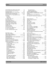
M
MAIN CHASSIS ASSEMBLIES ····7-16 -7 -19
Major Assemblies Location Diagram (Bottom View)
(Not 37397A)················2-8-2-9
Major Assemblies Location Diagram
(Top View)····················2-7
MANUAL SCOPE················1-3
MEASUREMENT ACCURACY ········4-4
Measurement Conditions Check List ·····5-23
Measurement Environment Considerations · · 4-6
MEASUREMENT IN QUESTION · · · 5-22 -5 -24
Measurement Technique ············4-7
Miscellaneous /Integrated Assemblies ·····2-6
O
ONLINE MANUAL ···············1-3
Operational Error Messages ··········B-3
OPERATIONAL ERROR MESSAGES·····B-3
Overall Block Digram of 373XXA VNA System 7-5
P
PARTS ORDERING INFORMATION· · 2-4 -2 -10
Performance Specifications ········D-1,1-1
Index-4 372XXB MM
E TO P INDEX


