


To replace the Floppy Disk Drive assembly, perform the steps above in
the reverse order.
8-12 REAR PANEL
ASSEMBLY
This paragraph provides instructions for removing and replacing the
Rear Panel Assembly.
Equipment Required Option 11 only):
q
Connector torque wrench (
5
16
in), ANRITSU Model 01-201, or
equivalent.
Preliminary:
q
Switch 373XXA power off. Remove the power cord.
q
Remove all covers (paragraph 8-3).
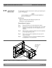
Remove/Replace Procedure:
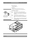
Step 1. Place the 373XXA in normal (top-side up) position.
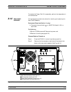
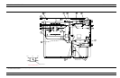
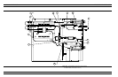
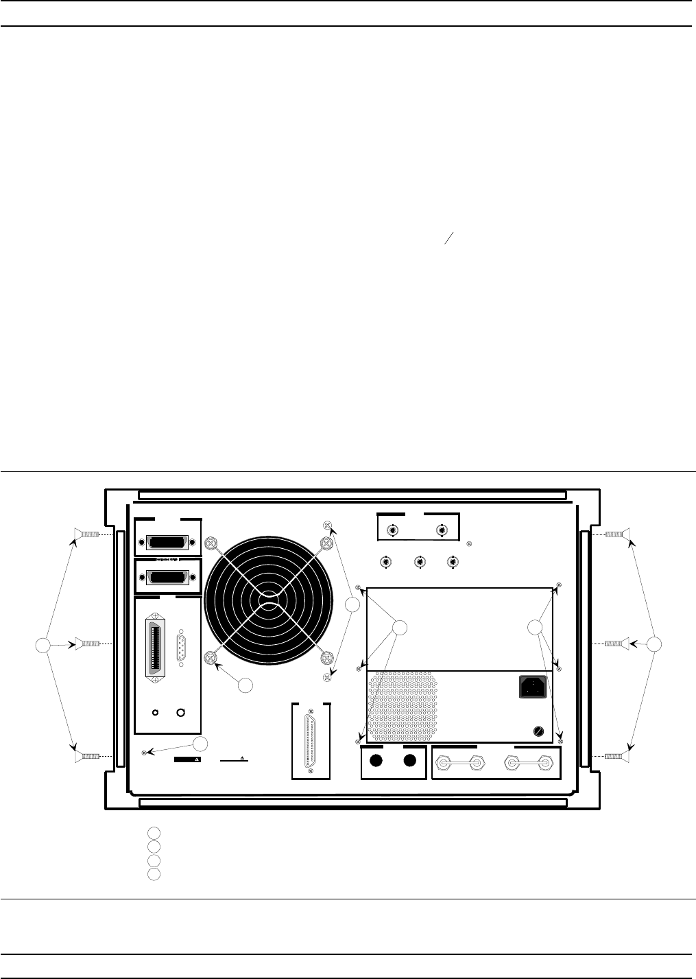
Step 2. Remove the three screws on each side of the chassis that
fasten to the rear panel assembly. See Figure 8-10.
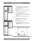
REMOVE AND REPLACE REAR PANEL ASSEMBLY
373XXA MM 8-19
External I/O
Reference Extension
RA In
RB In
RB Out
Display
IEEE 488.2 GPIB
10 MHz Ref
Εξτ
Ext
Trigger
Ext
AnlgIn
100-120V 5ASB
SAME TYPE AND RATING
85-264VAC48-63Hz
REPLACE FUSE ONLY WITH
540VA MAX
220-240V 2.5ASB
Bias Fuses
Port 1
Port 2
VGA OUT
PrinterOut
CRT Degauss
CRT Brt
WARNING
NO OPERATOR SERVICE-
ABLE PARTS INSIDE
REFER SERVICING TO
QUALIFIED PERSONNEL
CAUTION
FOR CONTINUED FIRE
PROTECT IONREPLACE
ONLY WITH SPECIFIED
TYPE AND RATED FUSE
SH1
AH1
T6
L4
SR1
RL1
PP1
DC1
DT1
C0
E2
Refer to manual
for GPIB address
RAOut
FUSE
FUSE
FUSE
FUSE
FUSE
FUSE
1n
±
5dBm 50
Ω
Out 0dBm 50
Ω
Ext
AnlgOut
1
2
4PL
1
1
3
3
4
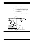
Rear Panel Assembly screws (par 8-11)
Fan Assembly screws (par 8-12)
Power Supply Assembly screws (par 8-13)
A18 Rear Panel PCB screw (par 8-14)
1
2
3
4
Figure 8-10. Location of Mounting Screws for Rear Panel Assemblies