


If calibration fails:
q
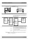
Verify the GPIB cable is connected to the Dedicated GPIB (bot
-
tom) connector on the 373XXA rear panel.
q
Verify that the frequency counter is functioning correctly, the ca
-
ble is in good condition, and all connections are secure.
q
Note which calibration step failed from the screen messages.
q
Repeat the calibration. If it still fails, then go to Chapter 5, Trou
-
bleshooting.
6-5 RF POWER/ALC
CALIBRATION
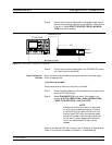
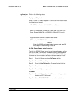
This procedure uses the 373XXA internal diagnostics and calibration
menus, in conjunction with a suitable power meter, to adjust the out
-
put power level of the signal source throughout the range of the
373XXA model being calibrated. Perform this calibration procedure if:
q
The Source Power/ALC test in Chapter 3, Operating Test, fails.
q
Other testing or troubleshooting reveals a possible problem with
RF Power accuracy or the ALC loop.
q
Any of the following assemblies are replaced:
n A21A1 Source YIG/Bias
n A21A2 Source Controller
n Down Converter
n YIG Oscillator
n Switched Filter
n
Transfer Switch
n
SDM (37369A)
n
Coupler (37325A and above)
n
Bridge (37317A and below)
n
Port 1 Source Step Attenuator
n
Buffer Amplifier
q
BBRAM chip on the A9 Processor PCB is replaced and the
Source Calibration Data was not previously saved on disk (thus
data could not be recalled from disk).
RF POWER/ALC CALIBRATION ADJUSTMENTS
6-8 373XXA MM