


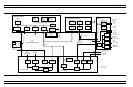
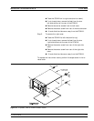
Power Supply Module The Power Supply Module is a single self contained assembly mounted
on the rear panel. This module provides:
q
Unregulated +5, +9, ±18, and ±27 Vdc supply voltages to the
other assemblies of the 372XXB.
q
Dedicated AC line connection for the Internal VGA Monitor.
q
Thermal and over-current shutdown protection circuitry
q
Sensing and input power regulation for operation with
85 – 264 VAC, 48 – 63 Hz, universal AC line input power.
q
Internal fan cooling (for power supply module)
q
Supply voltages distribution
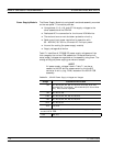
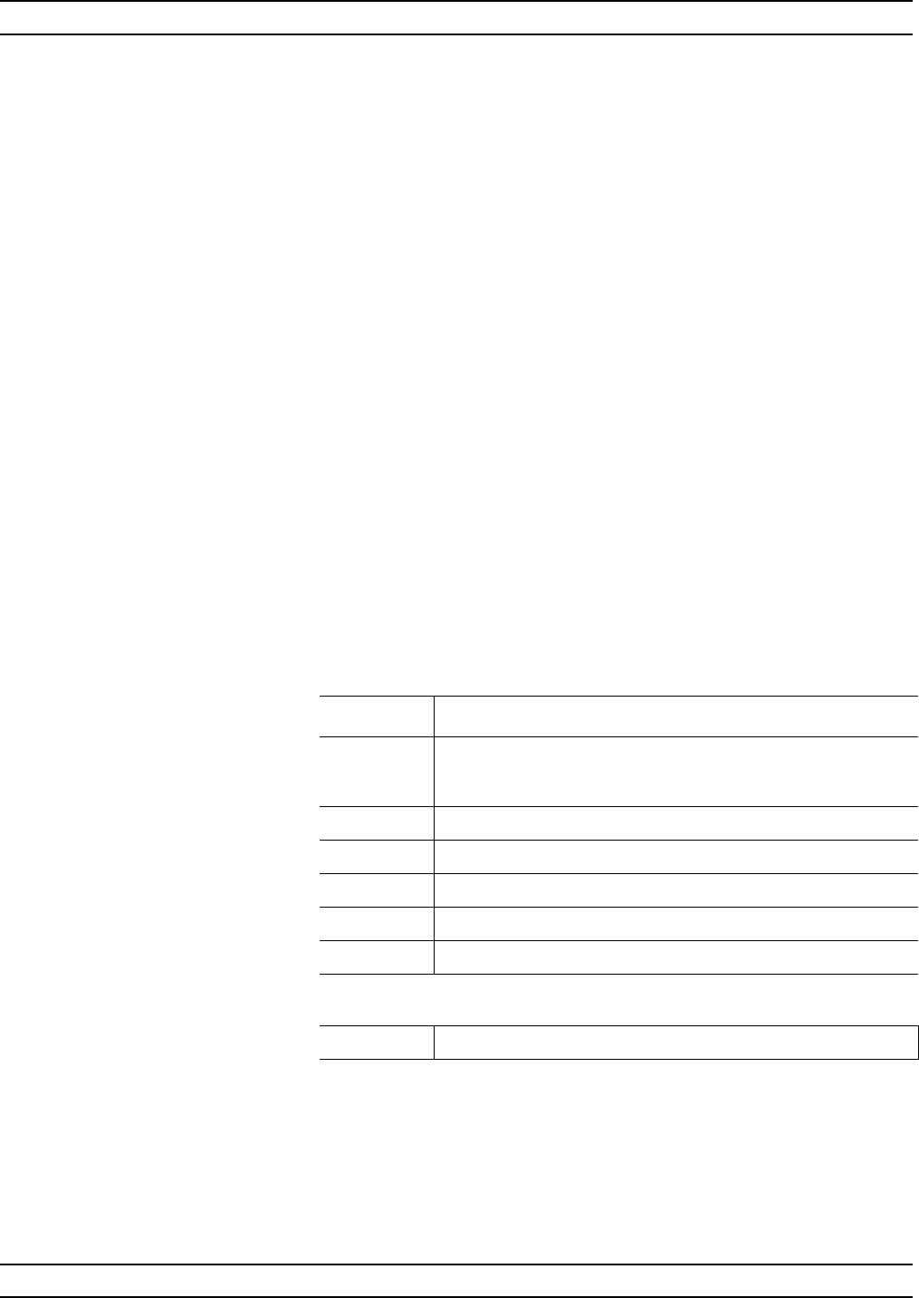
Table 7-1 identifies all 372XXB DC power supply voltages and lists
their usage by the various PCB assemblies. Unless otherwise indi
-
cated, supply voltages are regulated on the assembly using them. The
analog and digital power supply grounds are isolated.
NOTE
All power supply voltages listed in Table 7-1 can be ac-
cessed via the A/D bus for measurement by the the A/D
converter circuitry (e.g., DVM) located on the A5 A/D PCB
assembly.
MAIN CHASSIS ASSEMBLIES SYSTEM DESCRIPTION
7-18 373XXA MM
Voltage Assemblies Where Used
+5V A1, A2, A3, A4, A5, A6, A7, A9, A13, A14, A15, A16, A18,
A19/A20 (P.O. Front Panel), A21A1/A21A2 (P.O. Source Mod
-
ule), A24, External Keyboard
+9V A1, A2, A7, A8
+18V A1, A2, A3, A4, A5, A6, A7, A8, A13
-18V A1, A2, A3, A4, A5, A6, A7, A8, A13
+27V A1, A2, A5, A7
-27V A5, A18
The following supply voltages are derived from the +/-18 supply voltages on
the A13 I/O #1 PCB:
+12V A9, A15
Table 7-1. 372XXB Power Supply Voltages and Usages