


Step 2. Remove bottom panel, and lay the system down on its left
(monitor) side. Refer to Chapter 8, Remove and Replace
Procedures.
Step 3. Reconnect the power line input cord to the system and
Press the 373XXA Power key on.
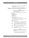
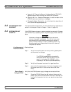
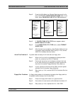
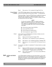
Step 4. Using a DMM or an oscilloscope, measure the DC power
supply voltages listed in Table 5-1. Connect the
DMM/oscilloscope to the top of the cable connectors at J13
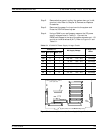
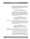
and J4 on the Motherboard (A17). Refer to Figure 5-1 and
Table 5-1.
TROUBLESHOOTING SYSTEM DOES NOT POWER-UP
373XXA MM 5-5
Connect To:
DC Supply Voltage
AC Ripple and
Noise
Conn Com (Pin) Meas (Pin)
J13 8 16 0 Vdc
50 mVpp
J13 8 1 +4.8 Vdc +1% / –0% 50 mVpp
J4 4 1 +9 Vdc +5% / –0% 100 mVpp
J4 4 6 +18 Vdc +10% / –0% 100 mVpp
J4 4 10 –18 Vdc +10% / –0% 100 mVpp
J4 4 12 +27 Vdc +5% / –0% 100 mVpp
J4 4 14 –27 Vdc +5% / –0% 100 mVpp
Table 5-1. 373XXA DC Power Supply Voltage Checks
J13
J4
1
1
14
16
372XXA A17 Motherboard D38517-3
(shown upside down)
Figure 5-1. Location of Connectors for Power Supply Voltage Checks